 English
 中文简体
 русский
 Español
 عربى

Who We Are

News & Updates
-
01
-
02






Mechanical Diaphragm Metering Pumps: Working Principle and Applications
Content
- 1 Mechanical Diaphragm Metering Pump: Operating Principles and Selection
- 2 1. The Role of Mechanical Diaphragm Metering Pumps
- 3 2. Mechanical Diaphragm Metering Pump Working Principle
- 4 3. Main Components and Their Functions
- 5 4. Industrial Applications and Dosing Requirements
- 6 5. Flow Adjustment and Performance Evaluation
- 7 6. Selecting a Pump for the Required Duty
- 8 7. Wetted Materials and Chemical Compatibility
- 9 8. Mechanical Diaphragm Pump and Alternative Metering Technologies
- 10 9. Understanding Operating Trends and Calibration
- 11 10. Integrating the Pump into a Dosing System
- 12 11. Maintenance Planning and Troubleshooting
- 13 12. Operational Reliability and Lifecycle Cost
- 14 13. Procurement Checklist for Industrial Buyers
- 15 14. Engineering Conclusions
- 16 15. Frequently Asked Questions
- 16.0.1 Q1: What is a mechanical diaphragm metering pump?
- 16.0.2 Q2: How does a mechanical diaphragm dosing pump work?
- 16.0.3 Q3: Which industries use mechanical diaphragm metering pumps?
- 16.0.4 Q4: How is the flow rate adjusted?
- 16.0.5 Q5: Are mechanical diaphragm pumps suitable for corrosive chemicals?
- 16.0.6 Q6: What causes a metering pump to deliver less liquid than expected?
- 16.0.7 Q7: Does the rated flow equal the actual delivered flow?
- 16.0.8 Q8: What is the difference between a mechanical diaphragm and a plunger metering pump?
- 16.0.9 Q9: Which accessories may be needed for a dosing system?
- 16.0.10 Q10: What information should buyers provide to a chemical dosing pump manufacturer?
- 17 Discuss Your Chemical Dosing Requirements
Mechanical Diaphragm Metering Pump: Operating Principles and Selection
A technical guide to positive displacement dosing, chemical compatibility, flow adjustment, system integration, and maintenance for industrial fluid handling.
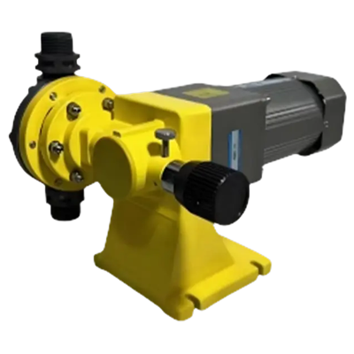
Mechanical diaphragm metering equipment used in controlled chemical dosing systems
1. The Role of Mechanical Diaphragm Metering Pumps
A mechanical diaphragm metering pump is a positive displacement pump designed to deliver controlled quantities of liquid into a process. It uses a mechanically driven diaphragm to create alternating suction and discharge strokes within a liquid chamber. Check valves direct the fluid through the chamber, allowing the equipment to deliver repeatable doses when the pump and connected system are correctly selected and operated.
These pumps are used when chemical addition must be controlled more carefully than ordinary liquid transfer. Typical duties include water treatment, industrial wastewater conditioning, pH adjustment, process chemical injection, and the addition of treatment agents to circulating liquids. Their suitability depends on flow demand, discharge pressure, fluid properties, material compatibility, and the control method required by the process.
The diaphragm separates the pumped liquid from the mechanical drive components. This arrangement can reduce the likelihood of process liquid entering the drive mechanism compared with certain direct-contact pumping arrangements. However, diaphragm integrity, valve sealing, connection quality, and the pressure limits of the complete system remain important to safe operation.
Understanding the relationship between mechanical movement and liquid flow helps engineers determine whether a mechanical diaphragm dosing pump can meet a particular process requirement. The equipment should be evaluated as part of a complete dosing installation rather than as an isolated pump body.
2. Mechanical Diaphragm Metering Pump Working Principle
The working principle relies on the repeated displacement of liquid by a flexible diaphragm. A motor supplies rotational motion, while a mechanical transmission converts that motion into the reciprocating movement required to operate the diaphragm. The changing volume of the liquid chamber creates alternating suction and discharge conditions.
How the suction and discharge strokes work
- Drive activation: The motor rotates the drive assembly, which transfers movement through a crank, connecting mechanism, or another manufacturer-defined transmission arrangement.
- Diaphragm retraction: During the suction portion of the cycle, the diaphragm moves to increase the available liquid chamber volume. The inlet check valve opens when the pressure conditions permit liquid to enter.
- Chamber filling: Liquid enters from the supply line. Reliable filling depends on the available inlet pressure, liquid viscosity, suction piping, and the operating speed of the pump.
- Diaphragm advancement: During the discharge portion, the diaphragm moves in the opposite direction, reducing chamber volume and increasing liquid pressure.
- Outlet delivery: The inlet valve closes and the discharge valve opens when the required pressure difference is established. A measured volume of liquid moves into the discharge piping.
- Cycle repetition: Repeated strokes create the overall dosing flow. The delivered quantity depends on the effective displacement per stroke, operating frequency, valve performance, and actual process conditions.
The actual valve timing is determined by pressure differences and the construction of the pump. The diagram illustrates the general cycle rather than a detailed sectional drawing of a particular model. In practice, the pump must have enough inlet supply to fill the chamber and sufficient discharge capability to overcome the downstream pressure.
Why positive displacement matters
A positive displacement mechanism moves a defined chamber volume during each operating cycle. This makes the pump suitable for dosing duties in which delivered volume needs to be adjusted and monitored. Nevertheless, theoretical displacement is not identical to measured output. Leakage through valves, incomplete chamber filling, diaphragm behavior, liquid compressibility, entrained gas, and discharge conditions can affect actual delivery.
Consequently, a pump that operates at a particular stroke setting does not automatically deliver the same flow under every installation condition. Commissioning should include an actual flow measurement using an appropriate calibration column, collection method, or suitable flow instrument.
3. Main Components and Their Functions
Reliable metering depends on several components working together. Failure or incorrect selection of one component can influence the performance of the complete dosing circuit.
Motor and Drive Mechanism
Provide the movement that operates the diaphragm. Motor selection must consider the power supply, operating duty, starting requirements, and environmental conditions.
Mechanical Diaphragm
Separates the pumped liquid from the drive assembly and changes the volume of the liquid chamber. Chemical compatibility, fatigue resistance, and pressure limits are essential.
Pump Head and Liquid Chamber
Contain the fluid during suction and discharge. Wetted construction materials must suit the chemical, its concentration, temperature, and cleaning requirements.
Inlet and Outlet Check Valves
Direct liquid through the intended path. Seat wear, contamination, incorrect assembly, and deposits can cause loss of prime or inconsistent dosing.
Flow Adjustment Mechanism
Changes the effective delivery through the available stroke-length or frequency adjustment. The supported adjustment method varies by model.
Seals and Connections
Maintain containment at joints and piping interfaces. Selection should account for chemical exposure, operating temperature, pressure, and maintenance access.
The motor, drive, diaphragm, valves, and liquid chamber establish the basic pumping function. Accessories such as injection fittings, strainers, pressure gauges, relief valves, and calibration equipment support installation and monitoring but do not replace correct pump sizing.
4. Industrial Applications and Dosing Requirements
A mechanical diaphragm dosing pump is typically selected for a specific chemical injection duty rather than for unrestricted liquid transfer. The most appropriate application is one where the required dosing range, pressure, fluid characteristics, and process control requirements are within the pump's verified operating limits.
Typical duty: Metering disinfectants, pH adjustment agents, coagulants, or other treatment chemicals where permitted by the process design.
Design consideration: Account for chemical concentration, injection pressure, water flow variation, and the control signal used to regulate dosing.
Typical duty: Feeding neutralization agents, flocculation chemicals, or treatment additives into process streams.
Design consideration: Prevent suspended matter from entering small valve passages and establish a cleaning schedule based on the actual fluid.
Typical duty: Supplying process additives, catalysts, inhibitors, and other compatible chemicals in controlled quantities.
Design consideration: Confirm material resistance, process pressure, temperature limits, and the consequences of underdosing or overdosing.
Typical duty: Feeding corrosion inhibitors, scale-control chemicals, and other water-treatment agents.
Design consideration: Relate dosing to system circulation, water quality, treatment requirements, and changes in operating load.
Typical duty: Metering compatible liquids into batch vessels, production lines, or continuous processing equipment.
Design consideration: Coordinate pump output with batch timing, process interlocks, and the need for repeatable delivery between production cycles.
Application suitability should never be inferred from the chemical name alone. Concentration, temperature, impurities, and contact time can significantly change material compatibility. Where the liquid is hazardous, volatile, highly corrosive, or otherwise difficult to handle, the system designer should verify the complete containment arrangement and applicable safety requirements before commissioning.
5. Flow Adjustment and Performance Evaluation
Flow adjustment is a central consideration when selecting a mechanical metering pump. Depending on the model, delivery may be adjusted through a manual stroke-length mechanism, variable operating frequency, or a compatible control arrangement. The permitted adjustment range and the effect of each adjustment must be confirmed in the manufacturer's technical documentation.
Reducing a setting does not necessarily preserve the same accuracy at every point in the operating range. At very low output, valve behavior, mechanical tolerances, fluid viscosity, gas accumulation, and measurement uncertainty may have a greater effect on the delivered quantity. A pump should therefore be evaluated at the actual intended operating point, not only at its nominal maximum capacity.
Factors Affecting Dosing Performance
Relative influence for a hypothetical installation. Scores are qualitative planning values, not measured industry statistics.
The chart provides a discussion framework rather than a universal ranking. In a clean, well-supplied installation, valve condition may be less influential than the selected control method. In a system with a restrictive suction line, inlet conditions may dominate. The engineer should identify the actual limiting factors through testing and operating observations.
Recommended performance checks
- Measure actual output at the intended operating setting.
- Repeat the measurement to identify variation between tests.
- Record the liquid temperature, concentration, suction conditions, and discharge pressure.
- Check for gas accumulation, unstable valve operation, leakage, and irregular discharge.
- Confirm that the lowest required dose remains controllable under normal operating conditions.
- Recheck performance after maintenance, piping changes, or significant changes in fluid properties.
6. Selecting a Pump for the Required Duty
Correct selection starts with the process requirement rather than the pump's advertised capacity. The engineer should establish the required minimum and maximum flow, normal discharge pressure, liquid characteristics, operating schedule, and method of control. The selected model must satisfy these requirements simultaneously.
| Selection Parameter | Information to Collect | Why It Matters |
|---|---|---|
| Required flow | Normal, minimum, maximum, and peak demand | Determines usable capacity and adjustment range |
| Discharge pressure | Process pressure, elevation, and piping losses | Establishes the pressure capability required |
| Liquid properties | Viscosity, density, solids, and tendency to release gas | Affects chamber filling and valve operation |
| Chemical compatibility | Identity, concentration, temperature, and contaminants | Guides wetted-material and seal selection |
| Suction arrangement | Tank level, line length, pipe diameter, and inlet restrictions | Helps prevent incomplete filling and loss of prime |
| Control strategy | Manual setting, remote command, or process-linked dosing | Determines the required adjustment and instrumentation |
| Operating environment | Ambient temperature, moisture, dust, and hazardous-area classification | Defines motor and installation requirements |
Establish a practical operating window
The selected pump should deliver the expected normal dose without remaining at an unsuitable extreme of its adjustment range. If a system needs a very small continuous dose and occasional high-volume delivery, one pump may not cover both conditions satisfactorily. Separate dosing arrangements, a different capacity range, or a revised control strategy may be more appropriate.
Discharge pressure must also be evaluated as a system requirement. The pump must overcome the pressure at the injection point and the losses through the discharge line, valves, and fittings. A pump's maximum rated pressure should not be treated as its normal operating pressure or as evidence that every accessory can withstand the same value.
For critical chemical applications, the design should also consider the consequences of an interruption in dosing. Depending on the process, suitable measures may include low-level detection, flow confirmation, alarm outputs, standby equipment, and interlocks that stop the process when required dosing cannot be confirmed.
7. Wetted Materials and Chemical Compatibility
Material selection is essential because chemical resistance depends on more than the general category of the pumped liquid. Concentration, temperature, impurities, exposure duration, and mechanical stress can all influence material behavior. A material that performs adequately with a dilute solution may not be appropriate for a concentrated solution of the same chemical.
Body and Chamber Materials
Polymeric and metallic materials may be considered according to the chemical, temperature, pressure, and mechanical requirements. Confirm compatibility with the complete wetted assembly rather than relying on a material name alone.
Flexible Barrier Material
The diaphragm must resist the liquid while tolerating repeated movement. Chemical attack, fatigue, pressure cycling, and excessive temperature can affect its service life.
Seats, Balls, and Springs
Valve components must provide suitable chemical resistance and reliable movement. Deposits, corrosion, wear, or sticking can reduce metering performance even when the diaphragm remains intact.
Gaskets and O-Rings
Seal materials should be checked for swelling, hardening, compression behavior, and compatibility at the actual operating temperature and concentration.
Before purchase, provide the pump supplier with the chemical name, concentration range, operating temperature, expected pressure, and any known contaminants. Where compatibility is uncertain, obtain documented material guidance or conduct an appropriate evaluation before introducing the liquid into the system.
For hazardous or corrosive liquids, containment planning should address leakage detection, safe drainage, access for maintenance, personal protective equipment, and the applicable handling procedures. Material compatibility alone does not establish that the overall installation is safe.
8. Mechanical Diaphragm Pump and Alternative Metering Technologies
Mechanical diaphragm pumps are one option within the broader metering pump category. Other technologies may be more suitable when a duty requires different pressure capability, liquid compatibility, accuracy characteristics, maintenance practices, or control flexibility. Comparisons should be made using the same process requirements and verified equipment data.
Typical Technology Characteristics
Qualitative illustration for preliminary screening. Actual performance varies by model, materials, and operating conditions.
The radar chart is a conceptual teaching aid, not a measured product comparison. Its values are illustrative and should not be used to rank equipment for procurement. The relative suitability of a technology changes with the pressure, flow range, chemical, and maintenance requirements of the specific duty.
Mechanical diaphragm metering pumps
These units use a mechanically actuated diaphragm and can be appropriate for routine chemical dosing when the duty is within the available capacity and pressure range. Their appeal often lies in a relatively straightforward mechanical arrangement, but the actual accuracy, adjustment range, and service life remain model-dependent.
Hydraulic diaphragm metering pumps
Hydraulic designs use an intermediate hydraulic system to actuate the diaphragm. Depending on the design, they may suit duties requiring a different pressure envelope or diaphragm loading arrangement. Their additional hydraulic components can influence maintenance procedures and troubleshooting requirements.
Plunger metering pumps
Plunger designs displace liquid through the movement of a piston or plunger. They may suit particular high-pressure or fluid-service requirements, but the liquid is in contact with the relevant sealing and packing arrangement. Leakage management, chemical compatibility, and the properties of the pumped liquid must be considered.
Selection should be based on verified duty-point data, chemical compatibility, control requirements, and lifecycle considerations. No technology is universally superior across every metering application.
9. Understanding Operating Trends and Calibration
Trend monitoring helps operators identify changes in output, control settings, and process demand. A flow trend should be interpreted alongside the operating conditions recorded at the same time. Without contextual information, an apparent reduction in delivery could reflect a process change, an adjustment, a measurement issue, or an equipment fault.
Illustrative Dosing Flow During Commissioning
Example measurements from a hypothetical calibration exercise, expressed as a percentage of a chosen reference output.
In the example, the measured output varies between consecutive checks. That variation should trigger a review of the test method and operating conditions rather than an immediate assumption that the pump is defective. Possible causes include inconsistent collection time, changes in pressure, trapped gas, incomplete priming, or valve behavior.
A practical calibration procedure
- Confirm that the installation is mechanically complete and all relevant safety measures are in place.
- Verify that the correct liquid or an approved calibration medium is being used under the specified conditions.
- Prime the pump and discharge line according to the equipment instructions, taking care to manage chemical exposure.
- Set the intended stroke and operating frequency, then allow the system to stabilize.
- Measure delivered volume over a suitable interval using a calibrated or otherwise appropriate measurement method.
- Repeat the test under the same conditions and compare the results for consistency.
- Record the settings, fluid properties, pressure, test duration, measured delivery, and any observed instability.
Calibration results should be retained as a baseline for later maintenance checks. If subsequent measurements depart from the baseline, repeat the measurement under comparable conditions before changing the control setting or replacing components.
10. Integrating the Pump into a Dosing System
A metering pump operates within a hydraulic and control system. Poorly arranged piping, inadequate inlet supply, unsuitable injection hardware, or missing pressure protection can undermine the pump's performance even when the pump itself is correctly selected.
The diagram represents a general arrangement. The exact location and configuration of isolation valves, relief devices, pulsation dampeners, pressure gauges, and injection accessories depend on the equipment instructions, fluid hazards, and system design. Relief discharge must be routed safely, and any pressure protection must be suitable for the potential failure conditions.
Suction piping considerations
- Keep the suction line as short and direct as practical.
- Use suitable pipe dimensions and fittings to avoid unnecessary inlet restriction.
- Ensure connections are airtight where air ingress could affect chamber filling.
- Evaluate the tank level and liquid properties across the expected operating range.
- Use a strainer only when appropriate for the liquid and the pump design, with a cleaning plan to prevent excessive restriction.
Discharge piping and injection
Discharge piping must withstand the expected operating pressure and relevant transient conditions. A pressure gauge can help with diagnosis, while a correctly sized relief arrangement can protect against dangerous overpressure when the discharge path is blocked. A back-pressure valve may be appropriate in some systems to maintain more stable operating conditions, but it must not be treated as a substitute for pressure relief protection.
Because reciprocating pumps can produce pulsating flow, the designer should assess whether pulsation affects downstream instrumentation, piping vibration, injection consistency, or process stability. A suitable pulsation dampener may reduce flow variation in an appropriately designed installation. Its selection and placement should follow system calculations and the equipment guidance.
11. Maintenance Planning and Troubleshooting
Preventive maintenance helps preserve dosing consistency and reduces the likelihood of unexpected process interruption. The inspection frequency should be based on the manufacturer's instructions, operating hours, liquid properties, duty severity, and the consequences of a dosing failure. A universal maintenance interval is not appropriate for every installation.
Routine Inspection Focus
Illustrative priority scores for organizing an inspection checklist. These scores are not failure-rate data.
Inspection priorities should be customized to the application. For a corrosive liquid, diaphragm and wetted-material condition may deserve greater attention. For a liquid that contains suspended particles, valve inspection and cleaning may be more frequent. For a remotely controlled dosing system, control signals and alarm functionality also need routine verification.
Common symptoms and possible causes
Troubleshooting should proceed from basic operating conditions to component inspection. Confirm liquid availability, pump settings, valve positions, and line condition before dismantling the equipment. If internal inspection is necessary, isolate the power supply, depressurize the system, drain or contain the liquid safely, and use the required protective equipment.
Do not continue operating a pump with suspected diaphragm damage or uncontrolled leakage. The response should follow the chemical hazard assessment and the equipment manufacturer's maintenance procedure. Replacement components must match the specified design and wetted-material requirements.
12. Operational Reliability and Lifecycle Cost
The purchase price is only one element of a metering system's lifecycle cost. Installation, energy use, calibration, replacement parts, labor, downtime, chemical losses, and disposal requirements can all affect the total cost of operation. The relative importance of each factor depends on the application and the consequences of a dosing interruption.
Build a maintenance and spares strategy
Identify the components most likely to require routine inspection or replacement according to the duty and equipment guidance. Common service items can include check-valve parts, diaphragms, seals, and other manufacturer-specified wear components. Keeping suitable spare parts available can reduce downtime where a failure would interrupt production or treatment.
Spare-part selection should be based on the exact pump model, material specification, and revision where applicable. A visually similar diaphragm or seal may have a different chemical resistance or mechanical rating. Procurement records should therefore connect the part to the installed equipment and the process liquid.
Monitor performance instead of relying only on run time
Operating-hour records are useful, but they do not reveal every condition that can affect a metering pump. Actual output checks, inspection findings, alarm history, and changes in process pressure provide additional evidence for maintenance decisions. A documented baseline makes it easier to distinguish gradual wear from a sudden process disturbance.
Where dosing is critical, maintenance planning should include the effect of equipment downtime, the availability of a standby pump, and the time needed to restore safe operation. Standby equipment should be installed and tested in a way that allows reliable changeover without introducing incompatible liquids or unintended dosing.
13. Procurement Checklist for Industrial Buyers
A clear technical inquiry enables a supplier to assess the duty more accurately and reduces the likelihood of selecting equipment that meets a nominal flow requirement but fails under actual site conditions.
- Required normal, minimum, and maximum dosing flow.
- Normal and maximum discharge pressure.
- Chemical identity, concentration, temperature, and relevant impurities.
- Supply tank arrangement and available suction conditions.
- Wetted-material requirements and compatibility restrictions.
- Required motor supply, operating frequency, and environmental protection.
- Manual adjustment, remote control, or process-linked dosing requirements.
- Required accessories, instrumentation, pressure protection, and injection hardware.
- Applicable installation, documentation, inspection, and compliance requirements.
- Expected operating schedule, maintenance access, and spare-parts needs.
Buyers should request the manufacturer's rated flow and pressure range, the conditions associated with those ratings, the available adjustment method, and relevant material compatibility information. Where dosing consistency is important, ask for the stated performance tolerance and the test conditions under which it applies. Do not assume that a nominal rating establishes performance at every flow setting.
For custom configurations, the inquiry should distinguish required features from preferences. This helps clarify which requirements affect safety, process compatibility, or performance and which relate to installation convenience. A complete technical review should also verify that the pump, motor, valves, piping, and protective devices are suitable for the same operating conditions.
14. Engineering Conclusions
Mechanical diaphragm metering pumps provide a practical approach to controlled chemical delivery in many industrial processes. Their operation depends on a reciprocating diaphragm, a liquid chamber, and check valves that manage suction and discharge. When properly selected, installed, and maintained, they can support repeatable dosing in water treatment, wastewater processing, chemical production, cooling systems, and other compatible applications.
Reliable performance requires more than choosing a rated flow. Engineers must consider the full operating window, inlet conditions, discharge pressure, fluid properties, wetted materials, and required control response. Calibration under representative conditions is essential for confirming delivered flow and creating a baseline for future checks.
For procurement teams, the most useful starting point is a clear duty specification backed by actual process data. Sharing this information allows the supplier to evaluate pump capacity, material compatibility, accessories, and control options against the intended service. The resulting selection should be verified as a complete dosing system, with suitable protection, maintenance access, and operating procedures.
15. Frequently Asked Questions
Q1: What is a mechanical diaphragm metering pump?
A mechanical diaphragm metering pump is a positive displacement pump that uses a mechanically actuated diaphragm to move controlled quantities of liquid. Check valves direct the flow through the liquid chamber during alternating suction and discharge strokes.
Q2: How does a mechanical diaphragm dosing pump work?
A motor drives a mechanical transmission that moves the diaphragm. Retraction increases the chamber volume and draws liquid through the inlet valve. The forward stroke reduces the chamber volume and pushes liquid through the outlet valve into the discharge line.
Q3: Which industries use mechanical diaphragm metering pumps?
Common applications include water and wastewater treatment, chemical processing, cooling water treatment, and general manufacturing. Suitability depends on the liquid, pressure, required flow, materials, and process control requirements.
Q4: How is the flow rate adjusted?
Depending on the pump design, flow may be adjusted through stroke length, operating frequency, or a compatible control arrangement. The adjustment method, permitted range, and performance at low output should be verified for the selected model.
Q5: Are mechanical diaphragm pumps suitable for corrosive chemicals?
They can be suitable when the diaphragm, pump head, valves, seals, and connections are compatible with the chemical at its actual concentration and operating temperature. Compatibility should be confirmed for the complete wetted assembly before use.
Q6: What causes a metering pump to deliver less liquid than expected?
Potential causes include inlet restriction, loss of prime, entrained gas, worn or contaminated check valves, unsuitable liquid properties, incorrect settings, and excessive discharge pressure. Actual flow measurement helps identify the cause.
Q7: Does the rated flow equal the actual delivered flow?
Not necessarily. Actual delivery depends on the operating point, chamber filling, valve performance, fluid properties, pressure conditions, and measurement method. Commissioning should verify output under representative process conditions.
Q8: What is the difference between a mechanical diaphragm and a plunger metering pump?
A mechanical diaphragm pump displaces liquid through the movement of a flexible barrier, while a plunger pump uses a moving plunger and its associated sealing arrangement. Their suitability differs according to pressure, fluid compatibility, leakage management, and maintenance requirements.
Q9: Which accessories may be needed for a dosing system?
Depending on the application, accessories may include injection fittings, isolation valves, pressure gauges, relief valves, back-pressure valves, pulsation dampeners, strainers, and calibration equipment. The final arrangement must follow the process risk assessment and equipment guidance.
Q10: What information should buyers provide to a chemical dosing pump manufacturer?
Provide the required flow range, operating and maximum pressure, chemical composition and concentration, liquid temperature, suction arrangement, wetted-material requirements, motor supply, control method, and installation environment. These details help the supplier assess the duty accurately.
Discuss Your Chemical Dosing Requirements
Share your target flow, operating pressure, chemical properties, and control requirements to support a technical review of the appropriate metering pump configuration.
Contact Us About Your Application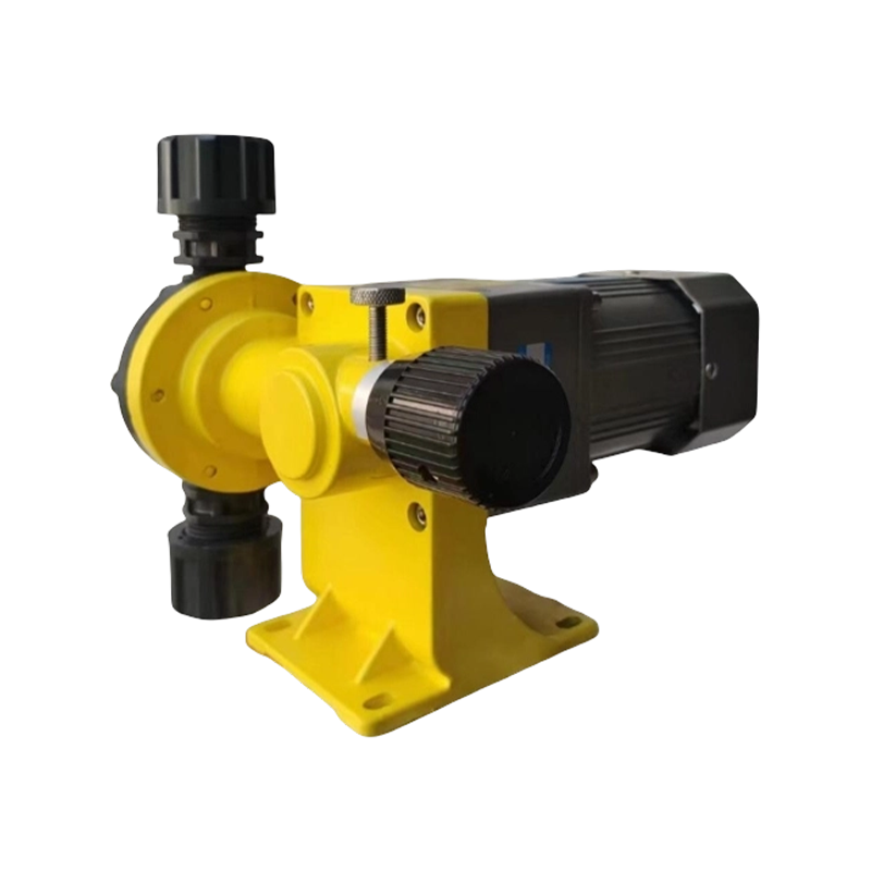
Launch your project from a free price list tailored to your needs.
Contact Us to Start Your Project.
Through standardized quality inspection procedures, we strictly control every link from raw materials to finished products, ensuring each product meets high-quality requirements.
+86-13861218983 Telephone
+86-13861218983 whatsapp
[email protected] Email
No. 89, Gehu Road, Gaocheng Town, Yixing City, Jiangsu Province, China Factory
Get in TouchCopyright © Jiangsu Syeelai Environmental Technology Co., Ltd. All rights reserved.Wholesale Chemical Transfer and Dosing Equipment Suppliers
