 English
 中文简体
 русский
 Español
 عربى

Who We Are

News & Updates
-
01
-
02






Plunger Metering Pump Flow Control and Industrial Applications
Content
- 1 Plunger Metering Pump Flow Control and High-Pressure Dosing
- 2 How a Plunger Metering Pump Controls Liquid Flow
- 3 Internal Structure and the Reciprocating Dosing Cycle
- 4 Flow Control Methods and Operating Characteristics
- 5 High-Pressure Dosing and Hydraulic System Design
- 6 Typical Industrial Chemical Dosing Applications
- 7 Flow Rate, Displacement, and Performance Verification
- 8 Plunger Metering Pump Selection Criteria
- 9 Performance Comparison Across Key Engineering Factors
- 10 Materials, Seals, and Liquid Compatibility
- 11 Installation Workflow and Commissioning Checks
- 12 Common Flow Problems and Troubleshooting
- 13 Maintenance Planning and Lifecycle Reliability
- 14 Operating Cost and Procurement Considerations
- 15 Engineering Checklist for a Reliable Dosing System
- 16 Frequently Asked Questions
- 16.0.1 Q1: What is a plunger metering pump used for?
- 16.0.2 Q2: How does a plunger dosing pump regulate flow?
- 16.0.3 Q3: Is a plunger metering pump suitable for high-pressure dosing?
- 16.0.4 Q4: What is the difference between a plunger pump and a diaphragm metering pump?
- 16.0.5 Q5: Which factors influence metering accuracy?
- 16.0.6 Q6: Can a plunger metering pump handle corrosive chemicals?
- 16.0.7 Q7: Why does a plunger metering pump deliver less flow than expected?
- 16.0.8 Q8: Is a pulsation dampener necessary?
- 16.0.9 Q9: What information is needed to select a high pressure metering pump?
- 16.0.10 Q10: How often should a plunger metering pump be maintained?
- 17 Discuss Your Industrial Dosing Requirements
Plunger Metering Pump Flow Control and High-Pressure Dosing
Understand reciprocating displacement, pressure management, flow adjustment, material compatibility, and practical selection criteria for industrial liquid dosing systems.
How a Plunger Metering Pump Controls Liquid Flow
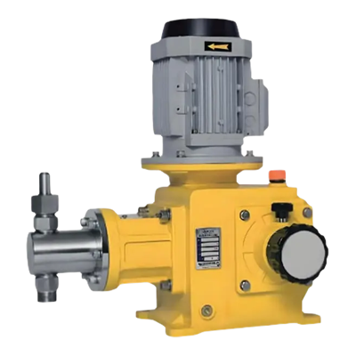
A plunger metering pump is a positive displacement pump designed to deliver a controlled quantity of liquid through a reciprocating plunger mechanism. It is commonly considered when a process requires a defined feed rate, elevated discharge pressure, or repeatable chemical injection into a pressurized pipeline, reactor, treatment unit, or industrial circulation system.
Unlike centrifugal pumps, which generate flow through rotational energy and hydraulic dynamics, a reciprocating plunger pump displaces liquid through the movement of a closely fitted plunger inside a pumping chamber. Inlet and discharge check valves direct the liquid through the intended flow path. The quantity delivered during each operating cycle depends on the effective displacement, stroke setting, operating frequency, valve behavior, and actual system conditions.
This mechanism makes the pump relevant to industrial liquid dosing applications where pressure and flow must be evaluated together. However, positive displacement does not automatically guarantee a particular dosing accuracy. Air entrainment, fluid viscosity, valve leakage, wear, pulsation, and changing backpressure can all affect actual delivery.
Liquid displacement through repeated plunger movement.
Adjustable operating variables subject to the pump design.
Both must remain within the equipment's rated limits.
A suitable pump must meet the required flow and discharge pressure simultaneously. A flow rating established at low pressure should not be assumed to remain unchanged under every high-pressure operating condition.
Internal Structure and the Reciprocating Dosing Cycle
The internal components determine how a plunger dosing pump draws in liquid, isolates the pumping chamber, and delivers the liquid against downstream pressure. Understanding these components helps maintenance personnel identify flow instability and helps engineers specify the correct configuration for an application.
Drive and motion conversion
The motor and drive mechanism convert rotational input into reciprocating motion. The transmission arrangement determines the available operating frequency, mechanical loading, and adjustment options.
Plunger and packing assembly
The plunger moves through a sealed interface that separates the pumping liquid from the surrounding mechanical structure. Packing design, surface condition, lubrication requirements, and maintenance access influence leakage control and service life.
Pumping chamber and check valves
The chamber receives liquid during the suction stroke and discharges it during the delivery stroke. Inlet and outlet check valves respond to pressure differences to control the direction of liquid movement.
Flow adjustment mechanism
Depending on the design, delivery can be adjusted through stroke length, stroke frequency, variable-speed operation, or an integrated control arrangement. Not every model supports every adjustment method.
What happens during one operating cycle?
Suction stroke
The plunger retracts, chamber pressure falls, and liquid enters through the inlet check valve when the available suction conditions permit.
Discharge stroke
The plunger advances, chamber pressure rises, the inlet valve closes, and liquid is delivered through the discharge valve when sufficient pressure is developed.
Repeated delivery
Successive cycles create the required average flow. Actual delivery depends on displacement, operating speed, volumetric efficiency, and system conditions.
The reciprocating action naturally creates flow pulsation. The degree of pulsation depends on the number of pumping elements, drive arrangement, stroke profile, operating conditions, and downstream hydraulic characteristics. Where smooth injection is important, a correctly sized pulsation dampener and suitable piping arrangement may be necessary.
Flow Control Methods and Operating Characteristics
Flow control begins with the required process feed rate, but the selected adjustment method should also account for pressure, liquid properties, dosing response, and the control system. A plunger metering pump may operate at a fixed setting or be integrated with a process controller to respond to changing demand.
Stroke length adjustment
Changing the effective plunger travel changes the displacement per cycle. This method is useful when the pump design supports a suitable adjustment range and the process requires a relatively stable operating frequency.
Check: Minimum controllable stroke, adjustment repeatability, and the manufacturer's permitted operating range.
Stroke frequency adjustment
Changing the number of operating cycles per unit of time changes the average liquid delivery. This approach can support remote control, process automation, and feed-rate adjustments based on measured demand.
Check: Drive compatibility, minimum and maximum speed, and valve response at the intended frequency.
Variable-speed control
A compatible variable-speed drive can regulate motor operation according to a process signal. The resulting flow response depends on the pump mechanism, transmission, speed range, and the relationship between operating frequency and delivered volume.
Check: Drive rating, torque requirements, cooling, and control stability.
Automatic process control
A controller can adjust a compatible pump using flow measurements, tank level, process concentration, or another relevant input. Closed-loop control is useful when the required feed rate changes with production conditions.
Check: Sensor accuracy, signal compatibility, response time, and fail-safe behavior.
Illustrative relationship between speed and flow
The following horizontal bar chart presents a hypothetical normalized example for a pump operating at three settings. It illustrates the expected relationship when effective displacement per cycle remains constant. The values are illustrative only and are not measured performance data for a specific pump.
Relative Flow at Different Operating Speeds
Relative index values demonstrate a proportional trend, not an actual capacity curve. Real delivery can deviate from this relationship because of valve dynamics, pressure, fluid characteristics, and pump condition.
Setting a practical operating point
- Define the normal, minimum, and maximum required dosing rates.
- Confirm that the desired flow range is within the pump's rated adjustment range.
- Verify discharge pressure at the actual injection point, including piping and equipment losses.
- Test delivery at representative operating conditions instead of relying solely on a nominal setting.
- Record the verified settings and establish a procedure for periodic flow checks.
High-Pressure Dosing and Hydraulic System Design
A high pressure metering pump is selected when the process requires liquid injection against substantial downstream resistance. Typical situations include pressurized treatment lines, chemical injection points, certain industrial reactors, and process equipment where the injection pressure must exceed the pressure already present in the receiving system.
The required discharge pressure is determined by the pressure at the injection point, static head where relevant, friction losses, restrictions, and the operating margin specified by the system designer. The pump must be rated for the required duty, and every pressure-containing component must remain within its permitted operating limit.
Rate the complete pressure boundary
Evaluate the pump head, plunger seal assembly, discharge piping, fittings, valves, pulsation dampener, pressure instrumentation, and injection accessories as a coordinated system.
Review before commissioning
- Maximum allowable working pressure
- Normal and transient operating pressure
- Relief and overpressure protection
- Seal leakage and inspection access
- Pressure gauge and transmitter range
Illustrative discharge-pressure comparison
The line chart below demonstrates how discharge pressure might vary across operating stages in a hypothetical process. The values are fictional examples intended to illustrate trend interpretation, not recommended pressure settings or measured pump performance.
Example Pressure Trend During Process Changes
An unexpected pressure increase can indicate a changing process demand, a partially restricted discharge path, a closed valve, or another hydraulic issue. Diagnosis must consider the full system rather than pressure alone.
Preventing overpressure
Positive displacement pumps can continue attempting to displace liquid when the discharge path is obstructed. If the system lacks suitable protection, pressure can rise beyond the safe rating of the weakest component. An appropriately selected pressure relief device and a safe return or discharge arrangement are therefore essential wherever required by the system design.
- Do not isolate a running pump between closed valves unless the approved system design explicitly permits the operating condition.
- Do not use a control valve as a substitute for correctly designed overpressure protection.
- Check the relief device setting against the lowest applicable pressure rating in the protected section.
- Provide safe depressurization and isolation procedures before maintenance.
- Investigate recurring pressure fluctuations instead of increasing the rated pressure without a full engineering review.
Typical Industrial Chemical Dosing Applications
A plunger dosing pump can serve several industries, but the suitability of a particular design depends on the liquid, flow range, injection pressure, operating cycle, and required level of control. The application should be defined by its process conditions rather than by the industry name alone.
Water and wastewater treatment
Metered chemical injection may be used for pH adjustment, treatment chemicals, process conditioning, and selected disinfection systems. Chemical compatibility and stable delivery are important where feed rate influences treatment performance.
Design focus: Feed consistency, chemical compatibility, suction stability, and safe containment.
Oil and gas processing
Process dosing may include corrosion inhibitors, scale-control agents, and other treatment chemicals injected into pressurized equipment or pipelines. The pump must accommodate the required injection pressure and the characteristics of the selected chemical.
Design focus: Pressure rating, hazardous-area requirements where applicable, and leak management.
Chemical manufacturing
Batch and continuous processes may require controlled additions of reactants, additives, or process-conditioning liquids. Repeatable dosing helps support consistent production conditions, provided that the measurement and control strategy is appropriate.
Design focus: Materials compatibility, turndown, batch repeatability, and maintenance access.
Industrial utilities and power systems
Selected utility systems use metering pumps for water conditioning and chemical treatment. In these installations, dosing reliability must be considered alongside pressure conditions, system availability, and monitoring requirements.
Design focus: Stable feed, monitoring, redundancy requirements, and service intervals.
Industrial cleaning and process lines
Controlled delivery of cleaning agents or conditioning liquids can be required in automated production and maintenance systems. The fluid's concentration, temperature, viscosity, and tendency to crystallize may affect the pump configuration.
Design focus: Flushing provisions, wetted materials, and compatibility with cleaning procedures.
Specialty liquid preparation
Processes involving concentrated additives or other specialized liquids may benefit from controlled positive displacement. Where the liquid contains suspended particles, the engineer must confirm that the valves, clearances, and seal arrangement are appropriate.
Design focus: Particle tolerance, seal life, fluid behavior, and required delivery stability.
Matching the application to pump requirements
The following matrix summarizes common selection priorities. It is a starting point for technical discussion, not a substitute for an application-specific equipment specification.
| Application | Primary requirement | Important operating concern |
|---|---|---|
| Water treatment | Repeatable chemical feed | Corrosion and chemical compatibility |
| Oil and gas | Injection against process pressure | Pressure integrity and leakage control |
| Chemical manufacturing | Controlled batch or continuous dosing | Material selection and feed stability |
| Industrial utilities | Reliable treatment feed | Monitoring and maintenance access |
| Cleaning systems | Controlled liquid delivery | Temperature, viscosity, and flushing |
Flow Rate, Displacement, and Performance Verification
The rated capacity of a reciprocating plunger pump is only one part of the selection process. Engineers should distinguish between theoretical displacement, the expected delivered flow, and the flow actually measured under operating conditions.
Theoretical displacement represents the liquid volume associated with the pump's geometry and movement. Actual delivery may be lower because of valve leakage, incomplete chamber filling, gas entrainment, seal wear, compressibility effects, or other hydraulic limitations. These effects can become more significant when operating conditions depart from those used for the original rating.
Illustrative capacity comparison
The column chart below uses hypothetical flow values to show how three example operating points can be compared during preliminary planning. These numbers are not product specifications and must not be used to select a real pump without verified manufacturer data.
Example Average Delivery by Operating Setting
Example values are for visualization only. Confirm actual capacity at the specified discharge pressure, liquid properties, adjustment range, and operating frequency.
How to verify delivered flow
Flow verification should be conducted using a suitable measurement method under controlled conditions. Depending on the liquid and installation, a calibrated collection vessel, weighing method, calibrated flowmeter, or another approved measurement approach may be appropriate.
- Confirm that the pump, piping, and downstream equipment are configured for the intended operating point.
- Check the suction supply and remove trapped air using the approved procedure.
- Allow the system to reach a stable operating condition before taking measurements.
- Record the pump setting, operating frequency, suction conditions, discharge pressure, and liquid temperature where relevant.
- Measure delivered quantity over a suitable period and repeat the test to assess consistency.
- Compare the measured result with the process requirement and the manufacturer's stated performance tolerance.
A documented baseline helps maintenance teams distinguish normal variation from gradual deterioration. If measured delivery changes, the recorded pressure, adjustment setting, fluid properties, and maintenance history provide a starting point for diagnosis.
Plunger Metering Pump Selection Criteria
Equipment selection should start with a written duty specification. The required flow rate, injection pressure, liquid properties, and operating pattern establish the main design envelope. Other requirements, including material compatibility, leakage control, instrumentation, and maintenance access, refine the final configuration.
Required flow and turndown
Define normal, minimum, and maximum flow requirements. Confirm that the intended operating points fall within the pump's validated adjustment range and that low-flow performance remains acceptable.
Discharge pressure and pressure variation
Specify normal and maximum operating pressure, including expected transients and the receiving system's pressure. Check the ratings of the pump and all associated pressure-containing components.
Fluid properties and materials
Document the liquid composition, concentration, viscosity, temperature, vapor pressure, solids content, and any tendency to crystallize or solidify. Select wetted materials and seals for the actual service conditions.
Suction conditions
Evaluate tank elevation, inlet piping, supply pressure, fluid temperature, and possible gas entrainment. An inadequate suction arrangement can prevent complete chamber filling and reduce delivery consistency.
Control and instrumentation
Identify whether manual adjustment, remote operation, variable-speed control, or automatic process feedback is needed. Specify compatible signals, measurement devices, alarms, and required interlocks.
Maintenance and service environment
Consider seal inspection, valve replacement, spare-part availability, operating hours, installation access, and environmental conditions. Equipment accessibility can influence long-term operating cost and downtime.
Comparing common pump technologies
A reciprocating plunger pump is not the best option for every liquid transfer duty. The following comparison highlights general characteristics and trade-offs. Actual performance depends on the particular design and operating conditions.
| Consideration | Plunger metering pump | Diaphragm metering pump | Centrifugal pump |
|---|---|---|---|
| Flow mechanism | Reciprocating plunger displacement | Flexible diaphragm displacement | Rotating impeller |
| Typical duty | Controlled delivery and pressure-oriented dosing | Controlled dosing with fluid isolation at the diaphragm | Continuous liquid transfer and circulation |
| Pressure behavior | Suitable designs can support high-pressure dosing | Depends on diaphragm and drive design | Depends on impeller design and operating point |
| Flow behavior | Reciprocating and potentially pulsating | Reciprocating and potentially pulsating | Generally continuous, with hydraulic variation |
| Key selection issue | Sealing, valve performance, and pressure rating | Diaphragm compatibility and integrity | System curve and required flow-pressure duty |
A plunger design may be suitable where the duty requires a defined feed rate at elevated pressure and the liquid is compatible with the plunger and packing arrangement. A diaphragm design may be preferable where the process requires separation between the pumped liquid and the drive mechanism. A centrifugal pump may be more appropriate for larger continuous transfer duties that do not require the same type of positive displacement metering.
Performance Comparison Across Key Engineering Factors
Procurement teams often need to compare candidate pump configurations across several technical dimensions. A radar chart can help organize these discussions, provided that its values are understood as qualitative planning scores rather than verified equipment ratings.
Qualitative Technology Comparison
The radar illustration is conceptual and not based on standardized tests. Actual scores can change substantially with model selection, materials, controls, operating conditions, and maintenance practices.
How to use a qualitative comparison
- Define the evaluation criteria before comparing equipment.
- Assign importance to pressure capability, metering range, leakage control, serviceability, and operating cost according to the application.
- Request model-specific curves, dimensional data, material specifications, and test records where applicable.
- Compare each candidate under the same defined operating conditions.
- Use the final duty specification to determine whether a qualitative preference is supported by verified technical data.
Materials, Seals, and Liquid Compatibility
Wetted material selection directly affects reliability in chemical dosing service. The pump body, plunger, packing, check valves, valve seats, gaskets, and associated piping may encounter different chemical exposure and mechanical stresses. Compatibility should therefore be checked for the complete wetted assembly rather than only the main pump body.
Metallic components
Metal selection should account for chemical concentration, temperature, contaminants, erosion, and pressure loading. A material that performs well with one chemical concentration may not be suitable for a more concentrated or hotter solution.
Plunger surface
Surface finish, dimensional condition, hardness, and corrosion resistance influence packing contact and wear. Abrasive particles or deposits can damage the sealing surface and increase leakage.
Packing and elastomers
Seal materials must be compatible with the liquid and its temperature range. Swelling, hardening, chemical attack, and excessive friction can reduce sealing performance and increase maintenance frequency.
Valve internals
Ball, seat, spring, and sealing materials must support reliable valve movement under the actual fluid conditions. Deposits, corrosion, or unsuitable clearances can cause delayed closure and reduced delivery.
Information required for compatibility review
Provide the pump supplier or application engineer with the chemical name, concentration, operating temperature, viscosity, solids content, and any relevant cleaning or flushing chemicals. If the liquid composition varies during production, identify the full expected range.
Where the liquid is hazardous, corrosive, toxic, or environmentally sensitive, consider containment, leakage detection, drainage, ventilation, and personnel exposure controls as part of the system design. Material compatibility alone does not establish that an installation is safe for the intended service.
Installation Workflow and Commissioning Checks
Correct installation is necessary to achieve stable dosing and reduce premature wear. A suitable pump can still perform poorly if the suction line is undersized, the liquid supply is unstable, the discharge piping is inadequately supported, or the control system is configured incorrectly.
From Process Requirements to Verified Operation
Follow the manufacturer's instructions and site safety procedures at every stage. Commissioning should be performed by qualified personnel with suitable protection and measurement equipment.
Pre-start inspection
- Confirm that the pump is correctly installed, aligned, anchored, and accessible for service.
- Check that the suction line is clean, the supply is adequate, and all required connections are correctly assembled.
- Verify that the discharge route is open and that valves are in their approved startup positions.
- Confirm that pressure relief protection, instrumentation, and required interlocks are installed and functional.
- Review motor direction, electrical connections, drive settings, and protective devices according to the manufacturer's instructions.
- Check for trapped air and follow the approved priming procedure before introducing normal operating loads.
Startup and operating confirmation
Start the equipment using the prescribed procedure and monitor unusual noise, vibration, temperature, pressure, and visible leakage. Verify that suction conditions remain stable and that the discharge pressure follows the expected operating pattern. Measure actual delivery at a representative setting and confirm that the control system responds correctly.
Do not loosen pressure-containing fittings or attempt to correct a leak while the system is pressurized. Isolate the equipment, release stored pressure through the approved route, and follow the site's lockout and maintenance procedures before intervention.
Common Flow Problems and Troubleshooting
Unstable delivery does not always indicate a fault inside the pump. Suction restrictions, inconsistent supply pressure, gas in the liquid, discharge blockage, unsuitable control settings, and downstream process changes can create similar symptoms. Troubleshooting should begin with a controlled review of the full hydraulic system.
| Observed symptom | Possible cause | Recommended investigation |
|---|---|---|
| Flow below expectation | Restricted suction, worn valves, seal wear, or incorrect adjustment | Verify suction conditions, settings, valve condition, and measured output. |
| Irregular discharge | Air entrainment, unstable feed, valve sticking, or pulsation effects | Check liquid supply, venting procedure, valve movement, and piping design. |
| Unexpected pressure rise | Blocked discharge, closed valve, or changing downstream resistance | Stop or isolate according to the operating procedure and inspect the protected system. |
| External leakage | Packing wear, damaged sealing surfaces, or incompatible materials | Use the approved shutdown and depressurization procedure before inspection. |
| Excessive vibration or noise | Mechanical looseness, poor alignment, cavitation-related conditions, or pulsation | Check mounting, drive condition, suction supply, and hydraulic accessories. |
| Flow changes with temperature | Viscosity variation, vapor formation, or seal behavior changes | Compare fluid temperature and properties with the specified operating envelope. |
Use evidence rather than repeated adjustment
Repeatedly increasing the stroke setting to compensate for low flow can conceal a deteriorating valve or suction problem. It may also create an excessive feed rate if the underlying condition suddenly clears. Record the symptom, operating conditions, measured flow, and recent maintenance work before making adjustments.
Where troubleshooting identifies internal wear, use the specified replacement parts and assembly procedures. After repair, perform the necessary leakage checks and flow verification before returning the equipment to normal service.
Maintenance Planning and Lifecycle Reliability
Preventive maintenance should be based on the manufacturer's recommendations, the severity of the application, observed component condition, and operating history. High-pressure service, abrasive liquids, long operating hours, or frequent adjustment may require a different maintenance strategy from intermittent low-duty dosing.
Inspect operating conditions
Monitor leakage, unusual noise, vibration, temperature, pressure behavior, and visible changes in the liquid supply. Record deviations from the established baseline.
Review wear components
Inspect packing, check valves, plunger surfaces, fasteners, lubrication points, and accessories according to the applicable maintenance schedule.
Verify actual delivery
Compare measured flow with the recorded commissioning result. Investigate significant changes and confirm that the process still operates within the specified envelope.
Prepare safe maintenance
Arrange isolation, depressurization, suitable replacement components, required tools, and documented restart checks before intrusive work begins.
Factors that influence maintenance intervals
- Liquid abrasiveness, corrosiveness, viscosity, and solids content.
- Operating pressure, frequency, and the proportion of time spent at demanding conditions.
- Seal material compatibility and the quality of the plunger surface.
- Inlet valve and discharge valve condition, including deposits or contamination.
- Availability of spare parts, maintenance personnel, and planned shutdown windows.
Maintenance intervals should not be assigned using a universal schedule without considering the equipment and process. Inspection findings and documented trends can support more effective planning, but safety-critical components must remain subject to applicable requirements and manufacturer guidance.
Operating Cost and Procurement Considerations
The purchase price of a metering pump is only one element of lifecycle cost. Total ownership considerations can include installation, controls, energy use, spare parts, scheduled service, process interruptions, liquid loss, and the cost of handling leakage or unstable dosing.
Initial equipment cost
Compare the pump, drive, control equipment, pressure accessories, instrumentation, and any required installation components as a complete package.
Energy and operating conditions
Evaluate the actual operating duty, motor selection, drive efficiency, and time spent at different flow and pressure conditions. Avoid estimating energy consumption from nominal capacity alone.
Maintenance expenditure
Consider seal and valve replacement frequency, technician time, access requirements, spare-part lead times, and the consequences of planned or unplanned downtime.
Process reliability
Unstable chemical feed can affect downstream process performance. Suitable monitoring, protective devices, and a verified operating range may reduce avoidable interruptions.
Information to include in a request for quotation
A detailed inquiry helps manufacturers assess the application accurately and reduces the risk of receiving quotations based on incompatible assumptions.
- Required minimum, normal, and maximum flow rates, with units.
- Normal and maximum discharge pressure and the pressure at the injection point.
- Liquid composition, concentration, viscosity, temperature, and solids content.
- Suction tank location, inlet pressure, piping arrangement, and supply conditions.
- Required materials for the pump head, plunger, valves, packing, and other wetted components.
- Manual or automatic control requirements, motor supply, and communication interfaces.
- Operating hours, environmental conditions, installation restrictions, and applicable safety requirements.
- Required documentation, inspection records, performance testing, and maintenance support.
When reviewing a quotation, confirm that the proposed operating point is supported by model-specific technical information. Ask which performance values are guaranteed, which conditions apply to the rating, and what testing is available to demonstrate delivered flow and pressure capability.
Engineering Checklist for a Reliable Dosing System
Before finalizing a pump specification, engineers and procurement teams can use the following checklist to confirm that the major operating requirements have been addressed.
Required flow range, operating schedule, batch or continuous service, and process response.
Suction supply, discharge pressure, piping losses, pressure transients, and relief protection.
Chemical composition, temperature, viscosity, solids, seals, and wetted materials.
Adjustment method, operating range, remote signals, process feedback, and alarm requirements.
Commissioning tests, flow measurement, maintenance intervals, replacement parts, and operating records.
A technically complete specification connects process needs with verifiable equipment performance. This approach helps identify unsuitable configurations early, supports a more meaningful supplier comparison, and provides a clear reference for installation and commissioning.
Frequently Asked Questions
Q1: What is a plunger metering pump used for?
A plunger metering pump delivers a controlled quantity of liquid through a reciprocating displacement mechanism. Common applications include chemical dosing, treatment processes, industrial injection systems, and selected pressurized process lines where flow control and pressure capability are important.
Q2: How does a plunger dosing pump regulate flow?
Flow can be regulated by adjusting the effective stroke length, operating frequency, or compatible variable-speed drive. The available methods depend on the specific design. Actual flow should be verified under the intended operating pressure and liquid conditions.
Q3: Is a plunger metering pump suitable for high-pressure dosing?
Some plunger metering pump designs are intended for high-pressure dosing. Suitability depends on the rated discharge pressure, required flow, fluid properties, seal configuration, and ratings of the connected piping and accessories. The complete operating duty must be checked before selection.
Q4: What is the difference between a plunger pump and a diaphragm metering pump?
A plunger pump moves a closely fitted plunger through a sealing assembly, while a diaphragm pump displaces liquid through the movement of a flexible diaphragm. A diaphragm can provide separation between the pumped liquid and the drive mechanism. The appropriate option depends on pressure, compatibility, leakage requirements, and the application.
Q5: Which factors influence metering accuracy?
Important factors include the pump's mechanical condition, valve sealing, stroke setting, operating frequency, suction stability, discharge pressure, fluid viscosity, entrained gas, and measurement method. A specified accuracy should be supported by manufacturer data and verified under defined test conditions.
Q6: Can a plunger metering pump handle corrosive chemicals?
It can handle compatible chemicals when the pump head, plunger, valves, packing, seals, and associated components are selected for the liquid's composition, concentration, and temperature. Compatibility must be checked for the complete wetted assembly rather than inferred from the body material alone.
Q7: Why does a plunger metering pump deliver less flow than expected?
Possible causes include restricted suction, gas entrainment, worn check valves, seal deterioration, incorrect adjustment, excessive viscosity, or unsuitable operating conditions. Compare measured delivery with the original baseline and investigate the complete hydraulic system before changing the pump setting.
Q8: Is a pulsation dampener necessary?
Not every installation requires a pulsation dampener, but it can be useful when reciprocating flow fluctuations affect instrumentation, piping vibration, injection stability, or downstream equipment. Selection depends on the pump arrangement, operating conditions, and system requirements.
Q9: What information is needed to select a high pressure metering pump?
Provide the required flow range, normal and maximum discharge pressure, liquid composition, concentration, viscosity, temperature, suction conditions, materials requirements, operating schedule, and control preferences. These details allow the proposed configuration to be assessed against the actual process duty.
Q10: How often should a plunger metering pump be maintained?
Maintenance frequency depends on the manufacturer's guidance, operating hours, pressure, liquid properties, seal and valve condition, and service environment. Routine inspection and periodic flow verification help identify deterioration. Use the equipment-specific maintenance schedule rather than applying a universal interval.
Discuss Your Industrial Dosing Requirements
Prepare your target flow rate, operating pressure, liquid properties, and control requirements to support a technical review of your metering pump application.
Contact Us for Technical Discussion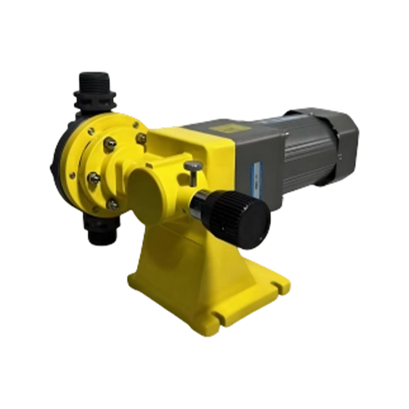
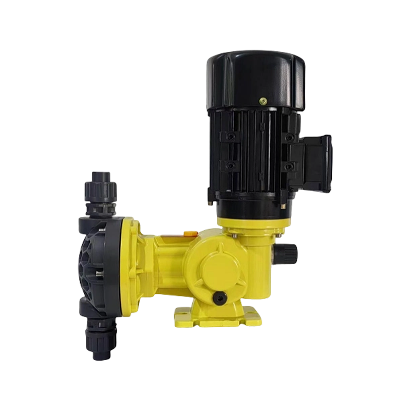
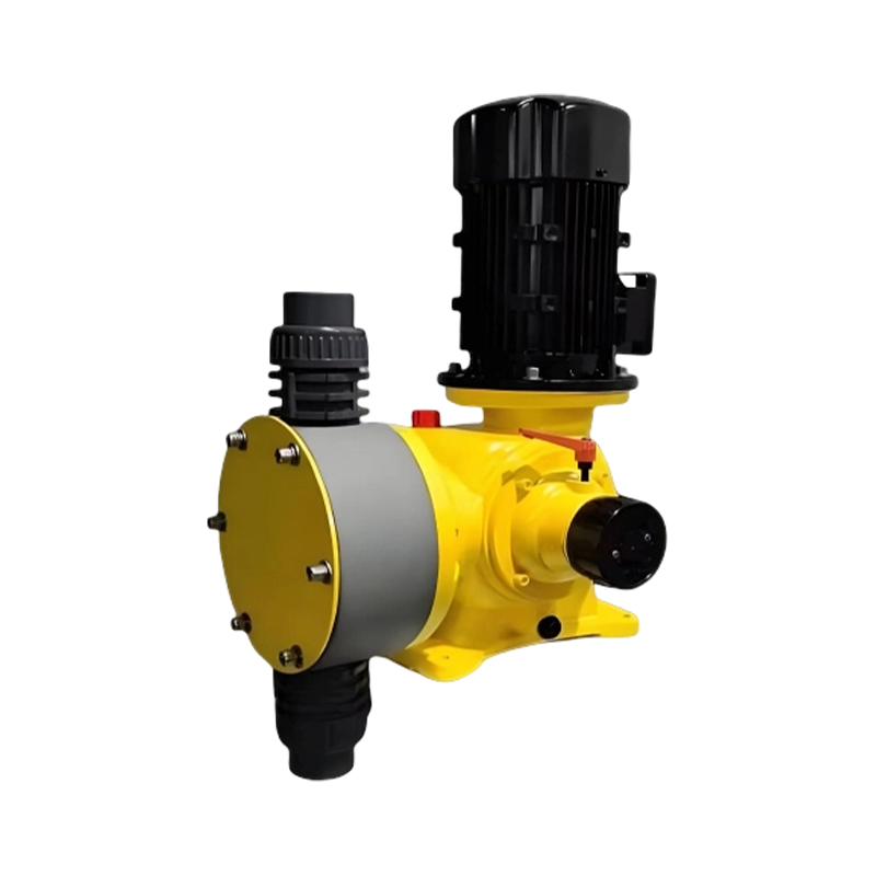
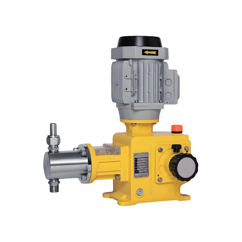
Launch your project from a free price list tailored to your needs.
Contact Us to Start Your Project.
Through standardized quality inspection procedures, we strictly control every link from raw materials to finished products, ensuring each product meets high-quality requirements.
+86-13861218983 Telephone
+86-13861218983 whatsapp
[email protected] Email
No. 89, Gehu Road, Gaocheng Town, Yixing City, Jiangsu Province, China Factory
Get in TouchCopyright © Jiangsu Syeelai Environmental Technology Co., Ltd. All rights reserved.Wholesale Chemical Transfer and Dosing Equipment Suppliers
