 English
 中文简体
 русский
 Español
 عربى

Who We Are

News & Updates
-
01
-
02






Metering Pump Pulsation Dampener for Chemical Dosing Systems
Content
- 1 Managing Pulsating Flow in Industrial Metering Systems
- 2 1. Why Pulsation Management Matters in Metering Pump Systems
- 3 2. Metering Pump Pulsation Dampener Working Principle
- 4 3. How Pulsation Dampeners Improve Pipeline Performance
- 5 4. Industrial Applications and Typical Operating Challenges
- 6 5. Key Factors in Pulsation Dampener Sizing
- 7 6. Comparing the Influence of Key Selection Variables
- 8 7. Common Pulsation Dampener Designs and Their Uses
- 9 8. Installation Position and Pipeline Integration
- 10 9. Comparing System Conditions Before and After Damping
- 11 10. Performance Verification and Troubleshooting
- 12 11. Maintenance Planning and Service Life
- 13 12. Technical Information to Provide When Sourcing a Dampener
- 14 13. A Practical Selection Workflow for Engineering Teams
- 15 14. Frequently Asked Questions
- 15.0.1 Q1: What is a metering pump pulsation dampener?
- 15.0.2 Q2: How does a metering pump pulsation dampener work?
- 15.0.3 Q3: Where should a pulsation dampener be installed?
- 15.0.4 Q4: Can a pulsation dampener eliminate all pipeline vibration?
- 15.0.5 Q5: How is a chemical dosing pulsation dampener sized?
- 15.0.6 Q6: Does a pulsation dampener replace a back pressure valve?
- 15.0.7 Q7: What materials are suitable for chemical dosing service?
- 15.0.8 Q8: How can pulsation dampener performance be verified?
- 15.0.9 Q9: What information should buyers provide when requesting a quotation?
- 15.0.10 Q10: What maintenance does a gas-charged pulsation dampener require?
- 16 15. Building a More Stable Metering Pump Pipeline
Managing Pulsating Flow in Industrial Metering Systems
Metering pumps deliver controlled liquid quantities through reciprocating or other cyclic displacement mechanisms. Although this operating principle supports accurate dosing, it can also produce periodic flow variations, pressure fluctuations, and mechanical loads throughout the connected pipeline.
A properly selected metering pump pulsation dampener helps reduce these variations by temporarily accommodating liquid displacement and releasing it as the pump delivery cycle changes. The result can be a more stable hydraulic operating environment for chemical injection, process control, and liquid transfer applications.
1. Why Pulsation Management Matters in Metering Pump Systems
Metering pump systems are commonly used in water treatment, chemical processing, pharmaceutical manufacturing, cooling water treatment, and industrial process control. Their purpose is to introduce a measured quantity of liquid into a process, often against an existing pipeline pressure.
However, the delivery rate of a reciprocating metering pump is not necessarily constant at every instant. During each pumping cycle, liquid enters the discharge line in a repeating pattern. The resulting fluctuations depend on the pump mechanism, operating speed, stroke characteristics, liquid properties, discharge pressure, and pipeline configuration.
Flow Variation
Periodic delivery changes can affect downstream flow measurement and injection consistency.
Pressure Fluctuation
Repeated pressure changes may increase the load on fittings, instruments, and pipeline connections.
Mechanical Vibration
Hydraulic pulsation can contribute to pipe movement, noise, and vibration-related maintenance issues.
The severity of these effects varies significantly between installations. A short, rigid discharge line operating at moderate pressure may behave differently from a long pipeline with multiple branches, flexible sections, or a sensitive downstream injection point.
2. Metering Pump Pulsation Dampener Working Principle
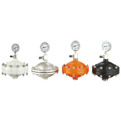
A pulsation dampener provides a degree of temporary storage and release within the liquid delivery system. Depending on its construction, it may use a gas cushion separated from the process liquid by a diaphragm, bladder, or other flexible element. Some designs use different internal arrangements to achieve a similar pressure-buffering function.
When discharge pressure rises during a pumping stroke, the dampener accommodates part of the incoming displacement. As the pump delivery rate decreases, the stored volume can return to the pipeline. This alternating response reduces the difference between peak and low flow conditions.
Figure 1. Simplified functional arrangement. Internal construction and connection details vary by dampener design.
2.1 During the Discharge Stroke
As the pump delivers liquid, the local pipeline pressure may rise. The dampener responds to this pressure increase by accepting a portion of the displaced liquid. In a gas-charged design, the gas volume compresses while the separating element moves in response to the liquid pressure.
2.2 During the Lower-Delivery Portion of the Cycle
When instantaneous pump delivery decreases, the pressure relationship between the dampener and pipeline changes. The dampener releases some of the accommodated liquid, supporting flow between successive discharge pulses.
2.3 Conditions Required for Effective Damping
- The selected dampener must be compatible with the pump's flow characteristics and operating pressure.
- The connection must allow effective hydraulic communication with the discharge line.
- Gas precharge, where applicable, must follow the equipment manufacturer's requirements.
- The internal wetted materials must tolerate the chemical composition and operating temperature.
- The installation must account for back pressure, pressure transients, and the presence of gas in the process liquid.
3. How Pulsation Dampeners Improve Pipeline Performance
The primary objective is to reduce undesirable variations, not to eliminate every pressure change under every operating condition. Actual performance depends on dampener sizing, location, internal design, pump frequency, and the hydraulic characteristics of the connected system.
Typical Relative Pressure Fluctuation Profile
Illustrative comparison of pressure variation during a repeating pump cycle.
Figure 2. Conceptual pressure profiles, not measured operating data. Actual waveform and attenuation depend on the installation.
3.1 More Stable Flow Delivery
In chemical dosing, variations in instantaneous flow can influence injection distribution, particularly when the chemical enters a process stream with limited mixing distance. A flow pulsation dampener helps smooth delivery across successive strokes, supporting more consistent downstream conditions.
3.2 Reduced Pressure Peaks
Repeated pressure peaks can contribute to fluctuating instrument readings, fitting loads, and unwanted mechanical movement. A correctly selected dampener can reduce these fluctuations, provided the pressure range and hydraulic response are suitable for the application.
3.3 Improved Measurement Conditions
Flowmeters and pressure transmitters may respond differently to pulsating flow depending on their measurement technology and installation. Dampening can improve signal stability, but the instrument's operating limits, minimum flow requirements, and installation instructions must still be observed.
3.4 Better Operating Conditions for Downstream Equipment
Control valves, injection quills, filters, and small-bore branches can be sensitive to cyclic pressure variation. Reducing excessive pulsation may help these components operate more consistently and reduce vibration-related maintenance demands.
4. Industrial Applications and Typical Operating Challenges
The required degree of pulsation control varies by industry. Chemical compatibility, injection accuracy, pipeline length, and the consequences of pressure variation are important considerations in every application.
Water and Wastewater Treatment
Coagulants, disinfectants, pH adjustment chemicals, and other treatment agents may be introduced through metering pump systems. Damping can support stable injection and improve the operating conditions of downstream measurement devices.
Chemical Processing
Acids, alkalis, solvents, and process additives may require controlled injection into pressurized lines. Wetted material compatibility and the relationship between pump discharge pressure and process pressure are critical.
Cooling Water Systems
Biocides, corrosion inhibitors, and scale-control chemicals are often dosed into circulation systems. Pressure stabilization can help reduce pulsation-related variation at injection and monitoring points.
Industrial Process Dosing
Metered additives used in manufacturing may require repeatable delivery under changing process conditions. Dampener selection should reflect the required dosing behavior and the system's operating range.
Application Example: A Long Chemical Injection Line
Consider a hypothetical treatment installation using a reciprocating metering pump to inject a corrosion inhibitor through a long discharge pipeline. The line includes several elbows, a pressure transmitter, an isolation valve, and a downstream injection point. Operators observe periodic movement in the pressure reading and vibration near a pipe support.
A suitable engineering assessment would examine the pump discharge waveform, the location of the pressure sensor, the pipe support arrangement, and the operating pressure range. Installing a dampener close to the pump discharge connection may reduce the pulsation transmitted into the line. However, pipe resonance, trapped gas, poor support design, or a partially obstructed line may also contribute to the symptoms and should not be overlooked.
5. Key Factors in Pulsation Dampener Sizing
Correct sizing is essential because a dampener that is too small may provide insufficient buffering, while an unsuitable internal design or operating configuration may produce limited improvement. The selection process should consider the pump, liquid, piping, and required degree of pressure stabilization together.
| Selection Factor | What to Assess | Why It Matters |
|---|---|---|
| Flow Rate | Average capacity and instantaneous discharge behavior | Determines the volume and flow variation requiring accommodation. |
| Operating Pressure | Normal, minimum, and maximum discharge pressure | Influences the pressure range and dampener operating conditions. |
| Pump Frequency | Stroke rate and number of discharge events | Affects the frequency of pulsation and the required hydraulic response. |
| Liquid Properties | Viscosity, density, solids, and gas content | Influences flow response, compatibility, and internal component selection. |
| Pipeline Layout | Length, diameter, branches, elbows, and flexible sections | Changes hydraulic resistance and pressure-wave behavior. |
| Required Attenuation | Permitted pressure variation and downstream process sensitivity | Defines the performance objective for selection and verification. |
5.1 Pump Capacity Is Only the Starting Point
Two pumps with the same nominal capacity may produce different pulsation patterns. A single-head pump and a multi-head configuration may have different discharge characteristics, while stroke adjustment and variable-speed operation can alter the delivery profile. Sizing based only on nominal flow can therefore lead to an unsuitable selection.
5.2 Operating Pressure and Precharge
For gas-charged dampeners, the precharge must be matched to the manufacturer's sizing method and the intended operating range. Incorrect precharge can reduce useful buffering, increase internal element movement, or prevent the dampener from responding as intended.
Precharge requirements are design-specific. The allowable charging medium, charging procedure, pressure limits, and inspection intervals should be confirmed in the product documentation rather than assumed from another dampener model.
5.3 Chemical and Temperature Compatibility
The process liquid contacts the wetted housing and, depending on the design, a diaphragm, bladder, seal, or other separation element. Material selection must account for the full chemical composition, concentration, temperature, pressure, and cleaning procedure.
Compatibility should be checked against documented chemical resistance information. A material that performs well in one concentration or temperature range may be unsuitable under different operating conditions.
6. Comparing the Influence of Key Selection Variables
The following visualizations are conceptual engineering aids. They illustrate how different variables can influence selection priorities; they are not test results, universal sizing values, or guarantees of dampening performance.
Relative Importance During Initial Assessment
Figure 3. Illustrative assessment priorities. Actual ranking depends on the process, safety requirements, and project specifications.
Conceptual Relationship Between Damping and Operating Conditions
Figure 4. A conceptual illustration of changing operating conditions. There is no universal curve relating operating conditions to attenuation.
For a real project, the most useful approach is to establish a measurable baseline, define an acceptable pressure variation, and obtain a sizing recommendation supported by the dampener's technical documentation or a hydraulic assessment.
7. Common Pulsation Dampener Designs and Their Uses
Pulsation dampers for pumps are available in several configurations. The appropriate type depends on pressure rating, liquid compatibility, maintenance requirements, installation space, and the degree of separation required between the process liquid and the gas or other buffering medium.
| Design Approach | Operating Characteristics | Selection Considerations |
|---|---|---|
| Diaphragm Type | A flexible diaphragm separates the process liquid from the gas cushion. | Check diaphragm compatibility, allowable movement, pressure rating, and replacement requirements. |
| Bladder Type | A flexible bladder accommodates liquid volume changes within the pressure vessel. | Review chemical exposure, temperature limits, gas precharge, and internal component life. |
| Direct Contact Gas Type | The buffering gas interacts directly with the liquid in designs intended for this arrangement. | Evaluate gas dissolution, process contamination, liquid aeration, and operating restrictions. |
| Specialized Damping Assembly | Uses a configuration tailored to a particular pump or process requirement. | Confirm operating envelope, connection dimensions, and documented performance data. |
7.1 Diaphragm and Bladder Separation
Separation-based designs are useful where direct contact between the process liquid and buffering gas is undesirable. The separating element is a critical component, and its material must be compatible with the liquid and expected operating conditions.
7.2 Direct Contact Arrangements
Some designs allow direct contact between the gas and process liquid. These configurations may be suitable for selected applications, but the possibility of gas dissolving into the liquid or entering downstream equipment must be assessed.
7.3 Design Selection Is Not Interchangeable
External appearance and nominal connection size do not establish functional equivalence. Two dampeners may differ in internal volume, effective compliance, pressure rating, material selection, and charging requirements. Substitution should be supported by engineering review rather than dimensional similarity alone.
8. Installation Position and Pipeline Integration
Installation has a direct influence on the effectiveness of a flow pulsation dampener. The component must be positioned and connected in a way that allows it to respond to the pressure fluctuations it is intended to control.
Recommended Installation Review Sequence
Confirm delivery characteristics and discharge pressure.
Identify restrictions, branches, and vibration points.
Follow the specified mounting and connection arrangement.
Compare pressure and flow behavior under defined conditions.
8.1 Position Relative to the Pump Discharge
For many reciprocating metering pump installations, the dampener is positioned near the discharge connection so that it can respond to the primary source of pulsation. The actual mounting arrangement should follow the equipment instructions and account for pipe loads, access, orientation, and maintenance clearance.
8.2 Isolation and Service Access
Where isolation valves are provided, their location and operating position must not unintentionally disconnect the dampener during normal operation. Any isolation arrangement should be compatible with the process safety design and maintenance procedure.
Gas-charged units require suitable access for inspection and charging checks. The installed equipment should remain accessible without forcing technicians to work around unsupported piping or hazardous chemical connections.
8.3 Pressure Relief and System Protection
A pulsation dampener is not a substitute for a pressure relief valve or other required overpressure protection. The discharge system must be assessed for blocked outlets, closed valves, process pressure changes, and other credible pressure hazards. Protection devices should be selected and installed according to the system design and applicable requirements.
8.4 Avoiding Common Installation Errors
- Mounting the unit in a position that restricts effective hydraulic communication.
- Using connecting pipework that introduces excessive resistance between the pump and dampener.
- Ignoring the specified gas precharge or charging procedure.
- Allowing pipe weight or vibration to load the dampener connection.
- Failing to provide safe access for inspection and maintenance.
- Assuming that a dampener will correct an incorrectly sized pipe or a mechanical support problem.
9. Comparing System Conditions Before and After Damping
A structured comparison helps engineers identify whether a pulsation control measure is addressing the actual problem. The following radar chart uses qualitative ratings solely to illustrate how several system characteristics may be evaluated.
Illustrative System Assessment
Figure 5. Qualitative illustration only. The ratings are not measured data and do not establish guaranteed improvements.
When evaluating an installation, use clearly defined measurements rather than relying on a visual impression. Record pump speed, stroke setting, operating pressure, liquid temperature, and process conditions so that comparisons remain meaningful.
Where practical, collect pressure measurements over enough pump cycles to identify both recurring pulsation and occasional transients. Instrument location and sensor response should be considered because a reading taken at one point may not represent the entire pipeline.
10. Performance Verification and Troubleshooting
After installation, commissioning should establish whether the dampener provides the intended reduction in pressure fluctuation without creating new operational problems. Verification is particularly important when dosing accuracy, pressure instrumentation, or downstream equipment performance is sensitive to cyclic flow.
Record Baseline Conditions
Document pressure variation, flow behavior, pump settings, and operating conditions before making changes whenever it is safe and practical to do so.
Inspect the Charging Condition
For gas-charged equipment, verify precharge using the specified safe procedure and suitable instrumentation. Do not open or charge a unit that remains pressurized with process liquid.
Review the Connection
Check for blockage, unintended isolation, loose supports, incorrect installation orientation, and other conditions that may prevent effective response.
Compare Operating Data
Repeat pressure and flow observations at comparable pump settings and process conditions. Record whether the measured change meets the project's acceptance criteria.
10.1 Persistent Pressure Fluctuation
If pressure fluctuations remain excessive, first confirm that the dampener is correctly sized and that the internal separation element is functioning as intended. Incorrect precharge, unsuitable connection geometry, excessive pump pulsation, and downstream hydraulic effects may all contribute to poor results.
10.2 Unexpected Noise or Vibration
Noise and vibration can result from pulsation, cavitation, loose supports, entrained gas, valve movement, or mechanical problems. A dampener may reduce one source of vibration without correcting other causes. Investigation should include the suction line, discharge line, pump mounting, and relevant valves.
10.3 Unstable Dosing or Measurement Signals
Check whether the observed variation is hydraulic or originates in the measuring instrument, control system, or process itself. Verify sensor placement, sampling behavior, and minimum operating requirements before attributing every unstable reading to the pump.
11. Maintenance Planning and Service Life
The maintenance requirements of a chemical dosing pulsation dampener depend on its internal construction, duty cycle, liquid compatibility, temperature, pressure, and service environment. Preventive inspection helps identify deterioration before it causes loss of damping performance or an unplanned shutdown.
| Inspection Area | Items to Review | Potential Warning Signs |
|---|---|---|
| External Housing | Corrosion, leakage, physical damage, and mounting condition | Visible deterioration, wet connections, or unusual movement. |
| Gas Precharge | Pressure condition and charging valve integrity where applicable | Loss of precharge or repeated pressure deviation from specification. |
| Internal Element | Diaphragm or bladder condition according to the service procedure | Loss of response, leakage, or evidence of material degradation. |
| Connections | Joint integrity, support, vibration, and signs of obstruction | Loose fittings, recurring vibration, or inconsistent pressure behavior. |
| Operating Performance | Pressure variation, flow behavior, and changes in process conditions | Increasing fluctuation or reduced stabilization compared with baseline. |
Inspection intervals should follow the manufacturer's recommendations and the site's maintenance strategy. More frequent checks may be appropriate for severe chemical service, frequent cycling, elevated temperature, or applications where a failure has significant safety or production consequences.
Before maintenance, isolate the equipment, depressurize the relevant system, and verify that stored energy has been safely released. Chemical residues and gas charging pressure may present hazards even when the pump is stopped. Only trained personnel should perform charging, disassembly, or pressure-boundary work using approved procedures.
12. Technical Information to Provide When Sourcing a Dampener
When evaluating metering pump pulsation dampener manufacturers and suppliers in China, buyers should provide enough application information to support a technically appropriate selection. A clear specification helps reduce avoidable changes during engineering review, procurement, and commissioning.
Pump Data
Nominal flow, pump type, operating speed, stroke settings, and discharge behavior.
Process Conditions
Liquid composition, concentration, temperature, viscosity, and expected operating range.
Pressure Requirements
Normal and maximum operating pressure, expected fluctuations, and design pressure.
Connection Details
Pipe size, connection standard, installation orientation, and available space.
Material Requirements
Wetted metal and elastomer compatibility, temperature limits, and cleaning conditions.
Performance Objective
Required pressure stability, downstream sensitivity, and any project-specific acceptance criteria.
12.1 Manufacturing and Documentation Review
Technical evaluation should extend beyond nominal size and quoted price. Buyers may need to review pressure ratings, material certificates where required, inspection procedures, charging instructions, dimensional drawings, and maintenance documentation.
For projects involving corrosive chemicals or demanding operating conditions, confirm that the proposed construction is supported by relevant material and design information. Any stated operating limits should be traceable to the technical documentation for the selected configuration.
12.2 Custom Requirements and System Integration
Some dosing installations require nonstandard connection arrangements, special wetted materials, or integration with existing pipeline assemblies. These requirements should be defined before manufacturing, with particular attention to pressure boundaries, installation clearance, applicable standards, and maintenance access.
Custom configurations should undergo the same technical review as standard equipment. Changes to connection dimensions or external geometry should not be assumed to preserve internal performance unless the design has been evaluated accordingly.
13. A Practical Selection Workflow for Engineering Teams
A repeatable selection process allows operators, engineers, and purchasing teams to evaluate the same operating requirements. It also helps separate a genuine pulsation problem from other sources of unstable pressure or flow.
Define the Problem
Determine whether the main concern is pressure fluctuation, flow variation, vibration, instrument instability, or a combination of effects.
Establish Operating Conditions
Collect pump data, process liquid properties, pipeline geometry, and the complete operating pressure range.
Evaluate the Dampener Design
Compare suitable internal designs, wetted materials, pressure ratings, mounting requirements, and maintenance procedures.
Confirm the Technical Proposal
Review sizing information, drawings, precharge requirements where applicable, and the documented operating envelope.
Verify Installed Performance
Use comparable operating conditions to establish whether the selected equipment meets the defined acceptance criteria.
For purchasing teams, this workflow provides a basis for comparing technically suitable proposals without relying solely on price or external appearance. For engineering teams, it establishes a documented link between the original problem, the selected design, and the commissioning results.
14. Frequently Asked Questions
Q1: What is a metering pump pulsation dampener?
A metering pump pulsation dampener is a hydraulic accessory designed to reduce cyclic flow and pressure fluctuations generated by a metering pump. Depending on its design, it temporarily accommodates part of the delivered liquid volume and releases it as pump delivery changes.
Q2: How does a metering pump pulsation dampener work?
When discharge pressure rises, the dampener accepts a portion of the liquid displacement. When pump delivery decreases, the stored volume can return to the pipeline. This response helps smooth the flow profile and reduce pressure variation.
Q3: Where should a pulsation dampener be installed?
For many reciprocating metering pump systems, the dampener is installed near the discharge connection. The final location should follow the equipment instructions and consider pipe geometry, isolation arrangements, pressure instrumentation, maintenance access, and safety requirements.
Q4: Can a pulsation dampener eliminate all pipeline vibration?
No. It can reduce vibration associated with hydraulic pulsation, but it cannot correct every cause of mechanical movement. Pipe resonance, inadequate supports, cavitation, loose connections, and mechanical faults may require separate investigation.
Q5: How is a chemical dosing pulsation dampener sized?
Selection considers pump capacity, instantaneous flow behavior, stroke frequency, operating pressure, liquid properties, pipeline configuration, and the required degree of pressure stabilization. Gas-charged designs also require an appropriate precharge based on the manufacturer's sizing method.
Q6: Does a pulsation dampener replace a back pressure valve?
No. A pulsation dampener primarily reduces cyclic flow and pressure variation, while a back pressure valve maintains a defined upstream pressure under suitable operating conditions. The components serve different functions and may be used together when the system design requires both.
Q7: What materials are suitable for chemical dosing service?
Suitable materials depend on chemical composition, concentration, temperature, operating pressure, and cleaning conditions. Wetted housing materials and internal flexible elements must be checked against documented compatibility data for the actual process liquid.
Q8: How can pulsation dampener performance be verified?
Record pressure and flow behavior before and after installation under comparable operating conditions. Check pump settings, instrument placement, dampener charging condition where applicable, and the acceptance criteria established for the project.
Q9: What information should buyers provide when requesting a quotation?
Provide pump type and capacity, operating pressure, liquid properties, temperature, connection dimensions, installation space, material requirements, and the desired level of pulsation reduction. Drawings and existing system data can further support technical evaluation.
Q10: What maintenance does a gas-charged pulsation dampener require?
Maintenance may include checking external condition, connection integrity, gas precharge, and internal element condition according to the manufacturer's procedure. Before inspection or service, the equipment must be isolated and depressurized using an approved safety procedure.
15. Building a More Stable Metering Pump Pipeline
Effective pulsation management begins with an understanding of the pump's delivery characteristics and the hydraulic behavior of the complete discharge system. A properly selected dampener can reduce recurring pressure variation, support more consistent flow delivery, and improve operating conditions for downstream instruments and equipment.
The most reliable results come from combining suitable sizing, chemical compatibility, correct installation, appropriate precharge where applicable, and performance verification under actual operating conditions. A systematic selection process also helps engineering and purchasing teams evaluate technical proposals against clearly defined requirements.
For industrial chemical dosing projects, reviewing the pump data, process conditions, pipeline arrangement, and required pressure stability provides a practical starting point for selecting an appropriate pulsation control arrangement.
Discuss Your Pulsation Control Requirements
Prepare your pump specifications, operating pressure, liquid properties, and connection details for a more focused technical review of your dosing system requirements.
Launch your project from a free price list tailored to your needs.
Contact Us to Start Your Project.
Through standardized quality inspection procedures, we strictly control every link from raw materials to finished products, ensuring each product meets high-quality requirements.
+86-13861218983 Telephone
+86-13861218983 whatsapp
[email protected] Email
No. 89, Gehu Road, Gaocheng Town, Yixing City, Jiangsu Province, China Factory
Get in TouchCopyright © Jiangsu Syeelai Environmental Technology Co., Ltd. All rights reserved.Wholesale Chemical Transfer and Dosing Equipment Suppliers
