 English
 中文简体
 русский
 Español
 عربى

Who We Are

News & Updates
-
01
-
02






Back Pressure Valves for Chemical Dosing Systems
Content
- 1 Back Pressure Control in Chemical Dosing Systems
- 2 1. Why Back Pressure Matters in Chemical Dosing
- 3 2. Main Functions of a Metering Pump Back Pressure Valve
- 4 3. Where Pressure Variations Commonly Affect Dosing
- 5 4. Back Pressure Valves and Other Pressure Control Devices
- 6 5. Applications Across Chemical Dosing Processes
- 7 6. How to Position a Back Pressure Valve in a Dosing System
- 8 7. Key Parameters for Back Pressure Valve Selection
- 9 8. Comparing Common Selection Priorities
- 10 9. Establishing and Verifying the Pressure Setting
- 11 10. Understanding Pressure Response During Operation
- 12 11. Practical Example: Dosing Into a Low-Pressure Tank
- 13 12. Common Problems and Corrective Checks
- 14 13. Inspection and Preventive Maintenance
- 15 14. How Correct Selection Supports Operating Efficiency
- 16 15. Pre-Purchase Technical Checklist
- 17 16. Frequently Asked Questions
- 17.0.1 Q1: What is the main purpose of a back pressure valve?
- 17.0.2 Q2: Is a back pressure valve necessary for every metering pump?
- 17.0.3 Q3: Can a back pressure valve prevent siphoning?
- 17.0.4 Q4: Can a back pressure valve replace a pressure relief valve?
- 17.0.5 Q5: How should the pressure setting be selected?
- 17.0.6 Q6: Which materials are suitable for chemical dosing?
- 17.0.7 Q7: Why does dosing remain unstable after installing a back pressure valve?
- 17.0.8 Q8: Where should the valve be installed?
- 17.0.9 Q9: How often should a back pressure valve be inspected?
- 17.0.10 Q10: What information is needed for technical selection?
- 18 17. Building a More Reliable Chemical Dosing Assembly
Back Pressure Control in Chemical Dosing Systems
Stable chemical injection depends on more than pump capacity. Discharge pressure, downstream resistance, liquid properties, injection conditions, and valve configuration all influence metering performance. A correctly selected back pressure valve helps establish suitable operating conditions for controlled chemical delivery.
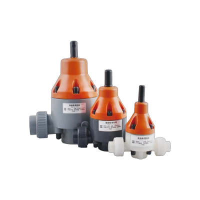
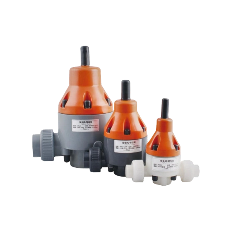
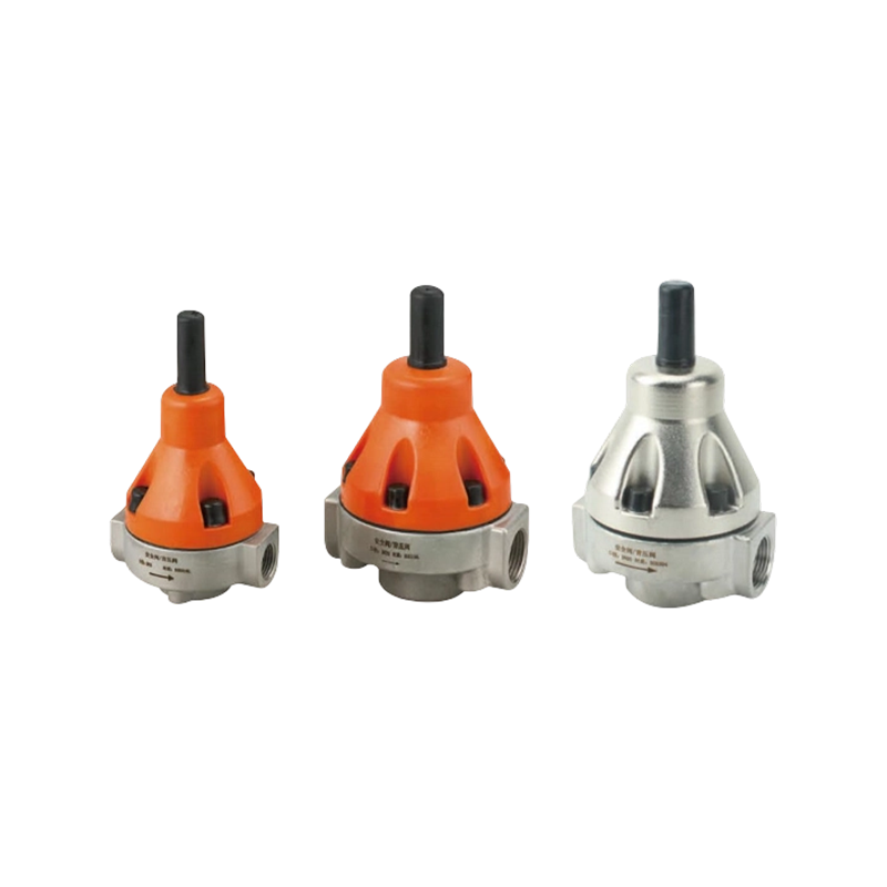
Typical accessories used in chemical metering and injection installations
1. Why Back Pressure Matters in Chemical Dosing
A chemical metering pump is designed to deliver a controlled volume of liquid, but its actual performance depends on the conditions surrounding the pump. When discharge pressure fluctuates, the liquid contains entrained gas, or the injection point offers insufficient resistance, the delivered quantity may differ from the expected setting. These effects become particularly important when dosing small quantities into a process with variable operating conditions.
Back pressure valves create a defined pressure threshold on the discharge side of a metering pump. They help maintain resistance against which the pump can operate, especially when the downstream line has low or changing pressure. Depending on the valve design, they can also help limit unwanted liquid movement when the pump is stopped and reduce the influence of downstream pressure variations on dosing behavior.
The valve is not a substitute for a correctly sized pump, a pressure relief device, or sound piping design. It performs a specific control function within a coordinated system. Selection should therefore consider the pump's operating range, maximum discharge pressure, injection point pressure, chemical compatibility, and the behavior of other installed accessories.
Evaluate the valve as part of the complete discharge assembly. A suitable pressure setting cannot compensate for an undersized pump, a blocked injection point, incorrect installation, or an unsuitable chemical-wetted material.
2. Main Functions of a Metering Pump Back Pressure Valve
Back pressure control supports several operating objectives. The relative importance of each function depends on whether the pump feeds a pressurized process, an atmospheric tank, a long transfer line, or a dosing point with changing pressure.
Maintain Discharge Resistance
The valve establishes a minimum pressure threshold so that a low-resistance discharge line does not leave the pump operating under unsuitable hydraulic conditions.
Improve Dosing Consistency
More consistent discharge conditions can reduce variations associated with low or fluctuating line pressure, particularly in systems sensitive to small dosing deviations.
Reduce Siphoning Risk
When the receiving point is below the chemical storage level, gravity may drive unintended flow. A suitably designed valve can help resist this condition, but its actual anti-siphon capability must be verified.
Support Injection Stability
A stable upstream pressure environment can help the injection assembly operate more consistently when process pressure changes within the system's permitted range.
These functions should not be interpreted as a guarantee of a particular dosing accuracy. Pump technology, calibration, liquid compressibility, suction conditions, check valve performance, pulsation, and maintenance all influence the final result. Pressure control is one part of a broader metering strategy.
3. Where Pressure Variations Commonly Affect Dosing
The following qualitative chart compares common operating disturbances by their potential influence on dosing consistency. The ratings are illustrative engineering guidance, not measured test results or universal performance specifications. Actual impact must be established from the process conditions and pump data.
Higher values indicate greater potential influence in this illustrative comparison, not a calculated risk score.
Pressure variation is especially relevant when the downstream process changes between operating states. Siphoning is more likely to become a concern when elevation and liquid head favor uncontrolled flow. Gas entrainment and suction restriction require attention at the pump inlet and cannot normally be resolved by a discharge back pressure valve alone.
4. Back Pressure Valves and Other Pressure Control Devices
Several accessories can appear similar in a dosing skid but perform different functions. Understanding these differences prevents the common mistake of selecting a valve based only on connection size or nominal pressure rating.
| Device | Primary Function | Typical Installation | Key Limitation |
|---|---|---|---|
| Back pressure valve | Maintains a defined upstream pressure threshold | Discharge line near the metering pump or dosing assembly | Does not independently protect against every overpressure event |
| Pressure relief valve | Opens to discharge or divert fluid when pressure exceeds its set threshold | Protected pressure zone, routed to a safe destination | Requires a suitable discharge path and correct relief sizing |
| Pressure reducing regulator | Controls downstream pressure relative to a higher upstream supply | Upstream of equipment requiring reduced supply pressure | Does not automatically provide the same function as a back pressure valve |
| Pulsation dampener | Reduces pressure and flow fluctuations associated with cyclic pumping | Discharge line, with location based on system design | Requires correct sizing and, where applicable, gas precharge management |
| Check valve | Restricts reverse flow | Line segments where one-way flow is required | Is not a substitute for a dedicated back pressure control device |
A back pressure valve may be used alongside a relief valve, pulsation dampener, check valve, or injection valve. The arrangement depends on the risk assessment and operating requirements. Relief protection is particularly important where positive displacement pumps can continue developing pressure against a blocked discharge.
5. Applications Across Chemical Dosing Processes
Back pressure control is relevant wherever a metering pump must deliver a controlled chemical quantity despite changes in downstream resistance. The valve's importance is determined by the operating conditions rather than by the industry name alone.
Water and Wastewater Treatment
Coagulants, disinfectants, pH adjustment chemicals, and other treatment agents may be injected into pipelines or tanks. A back pressure valve can help establish stable discharge conditions when the receiving point is at relatively low pressure. Chemical compatibility and the potential for deposits must be considered.
Industrial Process Chemical Injection
Process additives, corrosion inhibitors, and other treatment chemicals may enter pressurized process streams. The valve must be selected for the expected injection pressure and all credible pressure changes, including shutdown and startup conditions.
Cooling Water and Utility Systems
Scale inhibitors and biocide solutions may be dosed into circulating water systems. The receiving pressure can vary with pump operation, control valves, and network demand. Valve settings should be checked against the actual injection pressure range.
Batch Preparation and Transfer
When dosing into open tanks or low-pressure vessels, a metering pump may encounter limited downstream resistance. A properly specified back pressure valve can provide a defined operating threshold, while the system design must separately address siphoning and tank overflow risks.
For any application, confirm the chemical's concentration, temperature, viscosity, solids content, and tendency to crystallize or polymerize. A valve that performs adequately with clean water may behave differently with a viscous, abrasive, or deposit-forming process liquid.
6. How to Position a Back Pressure Valve in a Dosing System
Valve location influences the pressure conditions experienced by the pump and the stability of the complete dosing line. A typical arrangement places the back pressure valve in the discharge assembly, upstream of the injection point, with additional accessories positioned according to their own operating requirements.
Conceptual layout only. The required accessory order, isolation points, relief routing, and maintenance provisions must follow the equipment design and process safety requirements.
Installation principles
- Install the valve in the intended flow direction and follow the manufacturer's orientation requirements.
- Locate the valve where it can establish the intended pressure conditions without creating an isolated, unprotected pressure zone.
- Provide a suitable pressure relief path for positive displacement pump protection. Never rely on a back pressure valve alone to protect against a blocked discharge.
- Allow access for pressure measurement, adjustment, inspection, and safe maintenance.
- Consider whether a pulsation dampener, pressure gauge, isolation valve, or injection check valve is required elsewhere in the assembly.
7. Key Parameters for Back Pressure Valve Selection
Choosing a valve by nominal pipe size alone can result in unstable control, excessive pressure loss, leakage, or premature wear. The selection process should begin with operating data and proceed through hydraulic, mechanical, and chemical compatibility checks.
Operating and Maximum Pressure
Identify normal discharge pressure, minimum process pressure, maximum credible process pressure, and the pump's permitted discharge limit. Include startup, shutdown, and abnormal conditions.
Minimum and Maximum Flow
Check whether the valve can control reliably across the pump's actual operating range. A valve suited to a higher flow may be unstable at very low dosing rates.
Chemical Compatibility
Verify the body, diaphragm, seals, springs, and other wetted components against the chemical, concentration, temperature, and cleaning procedures.
Viscosity and Solids
Consider viscosity, suspended particles, crystallization, and deposits that may interfere with the internal moving parts or narrow flow passages.
Ports and Installation
Confirm connection type, nominal size, pressure class, available installation space, flow direction, and the requirements of adjacent fittings.
Adjustment and Repeatability
Review the adjustment range, setting method, stability at the intended flow, and the ease of verifying the operating pressure during commissioning.
Material selection should be based on documented compatibility rather than broad labels such as acid resistant or corrosion resistant. Compatibility can change with concentration, temperature, mixed chemicals, and exposure duration. Where the fluid is hazardous or unusually aggressive, obtain confirmation for every wetted component.
The selected valve must also tolerate the pressure and temperature envelope of the installation. A nominal setting range does not necessarily represent the maximum allowable pressure of the valve body or every connected component.
8. Comparing Common Selection Priorities
Different installations place different weight on pressure stability, chemical resistance, low-flow behavior, serviceability, and solids tolerance. The radar chart below provides an illustrative comparison of three generalized valve selection approaches. It is a planning aid rather than a ranking of actual products.
Illustrative relative scores are intended to prompt discussion of design priorities. They do not represent verified performance data or a substitute for technical specifications.
For clean, stable service, a general-purpose configuration may be sufficient if its pressure and material limits are appropriate. Aggressive chemicals require a more detailed compatibility review. Fluids containing solids or prone to deposits may require special internal geometry, more frequent inspection, or an alternative arrangement. No single configuration should be assumed to perform best across all five criteria.
9. Establishing and Verifying the Pressure Setting
The valve setting should be based on the pressure required for stable dosing under real operating conditions. It should not be selected as an arbitrary percentage of the pump's maximum pressure or adjusted until the system merely appears to run smoothly.
Recommended commissioning sequence
- Review the process data. Record the normal and expected range of injection point pressure, the pump's allowable discharge pressure, and the required dosing rate.
- Verify the assembly. Confirm flow direction, material compatibility, piping support, accessory positions, and the availability of suitable overpressure protection.
- Prepare the system safely. Follow the site procedure for filling, venting, flushing, and handling the chemical. Use a compatible test liquid where the procedure permits it.
- Start under controlled conditions. Operate at a suitable initial setting and increase the dosing rate and pressure in accordance with equipment instructions.
- Observe the pressure response. Check readings during startup, normal operation, changes in flow, and relevant process transitions. Look for unstable readings, leakage, and abnormal vibration.
- Verify actual delivery. Compare the delivered quantity with the required dosing rate using an appropriate calibration method. Pressure stability alone does not confirm volumetric accuracy.
- Document the final condition. Record the setting, flow range, process pressure, liquid conditions, and any limits identified during testing.
If the system cannot maintain the required delivery rate within the permitted pressure range, investigate the pump, suction line, injection point, and other accessories before increasing the setting. Excessive back pressure can increase mechanical loading and may exceed the allowable operating conditions of the pump or piping.
10. Understanding Pressure Response During Operation
A well-designed dosing assembly should respond predictably to changes in operating conditions. The following conceptual trend illustrates how a regulated discharge pressure may remain comparatively stable as downstream conditions vary within the valve's effective operating range. It is not a measured curve, and actual response depends on valve characteristics, flow rate, process pressure, and system configuration.
The curves are schematic and use relative values. They do not indicate a guaranteed pressure, response time, or dosing accuracy.
Pressure readings should be interpreted alongside flow measurements and the pump's operating status. A stable gauge reading can conceal a delivery problem caused by a blocked suction filter, gas accumulation, worn check valves, or a calibration issue. Conversely, short pressure fluctuations may arise from reciprocating pump pulsation and should be evaluated in relation to the instrument response and any installed dampener.
11. Practical Example: Dosing Into a Low-Pressure Tank
Consider an illustrative wastewater installation in which a metering pump transfers a treatment chemical from a storage tank into a receiving tank. The discharge line has little natural resistance, and the chemical storage level is above the injection point. Operators notice that delivery changes after the pump starts and that liquid may continue moving when the pump is stopped.
Uncontrolled Discharge Behavior
- Low resistance in the discharge line
- Potential gravity-driven flow
- Uncertain delivery after shutdown
- Limited pressure information
Review the Complete Assembly
- Evaluate a compatible back pressure valve
- Assess anti-siphon requirements separately
- Confirm relief protection and safe routing
- Measure delivery under operating conditions
The engineering review identifies the pressure required for reliable operation, confirms that the pump can deliver at that pressure, and checks that the valve's materials suit the treatment chemical. An anti-siphon arrangement is considered if the elevation and piping conditions create a gravity-flow risk. A separate relief device is verified to protect against blocked discharge.
Commissioning then compares actual delivery with the required rate at several representative operating conditions. If the delivery remains inconsistent, the team checks suction conditions, trapped gas, check valves, and calibration rather than assuming that a higher back pressure setting will solve every problem.
The lesson is that the valve can address a defined hydraulic issue, but it cannot independently correct every cause of dosing instability. A measured and documented commissioning process is more reliable than adjustment by observation alone.
12. Common Problems and Corrective Checks
When a dosing system performs poorly, troubleshooting should start with the observed symptom and verify the operating conditions before changing the valve setting. Increasing pressure without identifying the cause may worsen leakage, mechanical loading, or the consequences of a blocked line.
| Observed Symptom | Possible Cause | Recommended Check |
|---|---|---|
| Flow remains inconsistent | Unstable pressure, gas in the liquid, worn checks, or poor suction conditions | Measure delivery, inspect suction and discharge checks, and compare pressure readings |
| Pressure rises unexpectedly | Blocked injection point, closed isolation valve, or line restriction | Stop operation safely and inspect the discharge path and relief arrangement |
| Liquid moves after shutdown | Siphoning, gravity flow, or a leaking check valve | Assess elevation, line routing, valve function, and anti-siphon requirements |
| Valve cannot maintain the setting | Incorrect sizing, contamination, damaged internals, or unsuitable operating range | Check the manufacturer's operating limits, internal condition, and actual flow range |
| Leakage around connections | Incorrect assembly, chemical incompatibility, seal damage, or excessive pressure | Isolate and depressurize safely before checking seals, connections, and pressure limits |
| Frequent blockage or sticking | Crystallization, suspended solids, deposits, or chemical reaction | Review fluid properties, cleaning procedures, and suitability of the internal design |
Do not disassemble a pressurized valve or loosen a fitting to diagnose a suspected blockage. Follow the site's isolation, depressurization, flushing, and chemical handling procedures. Where the process fluid is hazardous, verify that trapped liquid has been safely contained before maintenance begins.
13. Inspection and Preventive Maintenance
Maintenance intervals should reflect the chemical, operating hours, pressure cycling, contamination risk, and consequences of failure. A universal interval is rarely suitable for every metering installation. Establish a baseline during commissioning and adjust the inspection frequency using observed condition and service history.
Observe
Monitor pressure readings, visible leakage, unusual noise, delivery changes, and any signs of external corrosion or deposit formation.
Verify
Check the pressure setting, connection integrity, instrument condition, and whether actual dosing performance remains within the process requirement.
Inspect Internals
When required by the manufacturer's instructions or service condition, examine diaphragms, seals, springs, and flow passages for wear, deposits, or chemical damage.
Recommission
Confirm correct assembly, leak tightness, pressure behavior, and delivered quantity before returning the system to normal service.
Replacement components should match the specified material and service requirements. Substituting a seal or diaphragm based only on matching dimensions can introduce compatibility or pressure-handling problems. Maintenance records should include the original symptom, inspection findings, parts replaced, setting after service, and the outcome of performance checks.
14. How Correct Selection Supports Operating Efficiency
The economic value of a back pressure valve is best evaluated through its contribution to stable operation and reduced corrective work. Purchase price is only one part of the overall cost. Incorrect sizing or material selection may lead to repeat adjustments, unplanned shutdowns, chemical waste, and more frequent maintenance.
Illustrative priority scores only. They are not survey results, cost estimates, or measured performance values. Actual priorities should be assigned by the project team.
Pressure compatibility and chemical compatibility are fundamental acceptance criteria, not optional benefits to be traded away for a lower initial cost. Service access and spare part availability also matter where maintenance windows are limited. A lifecycle review should consider expected inspection needs, replacement parts, downtime consequences, and the availability of qualified technical support.
For systems with critical chemical dosing duties, define acceptance criteria before procurement. These may include permitted pressure range, required flow range, wetted material compatibility, leakage expectations, adjustment method, and verification requirements. Clear specifications help avoid unsuitable substitutions and make commissioning results easier to assess.
15. Pre-Purchase Technical Checklist
Before selecting a back pressure valves configuration for a metering pump system, collect the information needed to confirm suitability.
Providing this information during technical review makes it easier to determine whether a standard configuration is suitable or whether the application needs a different material, pressure range, or accessory arrangement. Any final selection should be checked against current equipment documentation and the complete system design.
16. Frequently Asked Questions
Q1: What is the main purpose of a back pressure valve?
A back pressure valve maintains a defined pressure threshold upstream of the valve. In a chemical dosing system, it helps establish suitable discharge resistance and can improve operating consistency where downstream pressure is low or variable.
Q2: Is a back pressure valve necessary for every metering pump?
No. The need depends on the pump design, discharge pressure, injection point, line resistance, and risk of siphoning or unstable operation. The system designer should determine whether the valve is required from actual operating conditions and the pump manufacturer's guidance.
Q3: Can a back pressure valve prevent siphoning?
It can help resist unintended gravity-driven flow when the valve is designed and installed for that duty. However, not every back pressure valve provides verified anti-siphon performance. Elevation differences, line routing, and the need for a dedicated anti-siphon device must be assessed separately.
Q4: Can a back pressure valve replace a pressure relief valve?
No. A back pressure valve and a relief valve perform different functions. A positive displacement metering pump may continue to develop pressure if the discharge becomes blocked, so suitable overpressure protection must be provided according to the system design.
Q5: How should the pressure setting be selected?
The setting should support stable dosing while remaining within the allowable pressure limits of the pump, valve, piping, and other components. Consider the normal injection pressure, changes in process conditions, required flow, and the manufacturer's instructions. Verify the result during commissioning.
Q6: Which materials are suitable for chemical dosing?
Suitable materials depend on the chemical, concentration, temperature, contamination, and cleaning conditions. The valve body and every wetted seal, diaphragm, and internal component should be reviewed individually against documented compatibility information.
Q7: Why does dosing remain unstable after installing a back pressure valve?
Other causes may include gas in the liquid, suction restrictions, worn check valves, pump calibration errors, pulsation, an unsuitable valve operating range, or a blocked injection point. Check actual delivery and pressure behavior before making further adjustments.
Q8: Where should the valve be installed?
It is generally installed in the discharge assembly upstream of the injection point, but the exact location depends on the equipment design and accessory arrangement. Follow the required flow direction and ensure that all pressure zones have appropriate protection and maintenance access.
Q9: How often should a back pressure valve be inspected?
Inspection frequency depends on operating hours, chemical aggressiveness, contamination risk, pressure cycling, and the consequences of failure. Use the manufacturer's maintenance guidance and adjust the schedule according to commissioning observations and service history.
Q10: What information is needed for technical selection?
Provide the required flow range, operating and maximum pressure, pump specifications, chemical properties, wetted material requirements, connection details, process conditions, and potential abnormal operating scenarios. These details support a more reliable compatibility and sizing review.
17. Building a More Reliable Chemical Dosing Assembly
Reliable chemical injection requires coordinated control of pressure, flow, chemical compatibility, and mechanical protection. A back pressure valve can help maintain suitable discharge conditions, reduce the effects of low line resistance, and support consistent metering when selected for the actual operating range.
The most dependable approach combines verified pump capacity, appropriate valve sizing, compatible wetted materials, correct accessory placement, pressure relief protection, and measured commissioning. When abnormal behavior occurs, troubleshooting should examine the entire dosing system rather than relying on pressure adjustment alone.
Reviewing these factors before procurement helps engineers and purchasing teams define clear technical requirements, reduce avoidable installation issues, and establish a practical maintenance plan for long-term operation.
Review Your Chemical Dosing Requirements
Prepare your operating pressure, flow range, chemical properties, and connection requirements for a more focused technical discussion about valve suitability.
Launch your project from a free price list tailored to your needs.
Contact Us to Start Your Project.
Through standardized quality inspection procedures, we strictly control every link from raw materials to finished products, ensuring each product meets high-quality requirements.
+86-13861218983 Telephone
+86-13861218983 whatsapp
[email protected] Email
No. 89, Gehu Road, Gaocheng Town, Yixing City, Jiangsu Province, China Factory
Get in TouchCopyright © Jiangsu Syeelai Environmental Technology Co., Ltd. All rights reserved.Wholesale Chemical Transfer and Dosing Equipment Suppliers
